ANENG AC2 Mains tester
Started 4th December 2021
When I was a child I hankered after an "illuminated screwdriver", in other words a mains neon tester, surely the inspiration for Dr Who's "sonic screwdriver". In these the screwdriver blade is connected in series with a neon tube and a resistor, the idea is that if you hold the blade to live mains and touch the contact on the other end of the screwdriver the neon will light as electricity leaks to earth through you.
Does that sound like a bad idea? By now they're frowned upon. All those heroic tales in Practical Television of fixing live chassis TVs with one, consigned to history.
I bought the 21st century equivalent "ANENG Digital Tester Pencil non-contact saft Test Pen AC DC 12-250V Tester Electrical LCD Display Screwdriver Voltage Indicator". I was not expecting this to be any safer than my screwdriver.
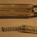
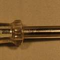
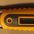
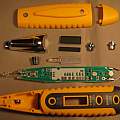
In the photos after the screwdriver style blade at the far left in the shiny metal area there is a white LED and a button, press the button and a switch is activated to turn the LED on. Coming further right there is what looks like a round LED and then an LCD screen - in fact there is one LED and a light guide which lights up the round "LED" and back-lights the LCD.
Moving on there is a button "induction", this is not a switch activating button, but a contact, the metalised plastic is a good conductor and touching the button you are connected to the circuit board in the tester. This is the equivalent of the metal conductor you touch on the top of the old neon screwdriver. The other side of the circuit board is connected to the AC2 blade.
Finally there is a similar button style contact "direct" this connects the positive rail voltage to you from the batteries in the tester for something like a DC continuity test.
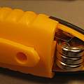
Photo 3 shows how to insert the three batteries.
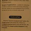
Photos of the accompanying card.
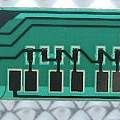
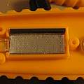
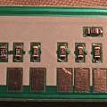
The insides. Photo 3 shows how the conductive strip is inserted on edge, bridging between the LCD and the seven metal pads on the PCB.
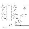
One transistor is marked M6 , a PNP transistor, with BCE (132) ordering, looked at from above with the side with the single pin 3 at the top. The other is marked L6, an NPN transistor, with the same pinout. The schematic below shows that these two transistors form a complementary Darlington (or Sziklai) pair.
I'd rather poke my neon screwdriver into a mains socket than the AC2 if I really had to. Where the AC2 is better is being able to detect mains voltage without making direct electrical contact. That's due to its built in amplification, with actual mains voltage present the problem for the designers will have been reducing voltage.
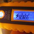
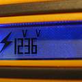
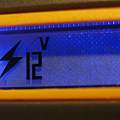
The greater the signal the more LCD segments appear. The lowest level is just the flash symbol. The LCD segments will appear even when there are no batteries in the tester.
To take the photos I touched the AC2 to one side of a low voltage power supply. Most of the switching power supplies that are now common for phone chargers and the like, have a very low current connection to mains voltage on their outputs, enough to light my neon screwdriver.
It is very easy to touch the direct button instead of the induction button - it makes little difference to results - but your connection to the screwdriver blade is shorter.
David Pilling's Wiki
Set view
