Arduino 32768
Started January 2015
Browsing the Atmel AVR datasheet one soon picks up references to using 32768 Hz watch or clock crystals with the chips. The idea is that these will give accurate time keeping whilst allowing low power operation. No doubt lots of people have explored this idea but I could not find a complete account.
I set out to modify an Arduino Pro Mini with Atmega 328p processor running at 8 MHz and 3.3 V. Other Atmega chips may allow a 32768 Hz crystal to be used at the same time as the normal clock crystal.
These are the steps
- For 16 MHz boards burn an 8 MHz boot loader (or else see 'Bricked')
- Set the fuses on the processor so that it uses its internal 8 MHz RC oscillator for a clock
- Disconnect the normal crystal/resonator
- Connect a watch/clock crystal
- Upload suitable software
I set the fuses by connecting a USBASPI programmer to the Pro Mini, and then used this command line (for avrdude):avrdude -p m328p -c usbasp -P USB -U lfuse:w:0xE2:m
I wanted to remove the power regulator and power LED to reduce power consumption and thought I could remove the crystal at the same time. A fine soldering iron was not good enough, I might as well have chiselled the components off the board with a small screwdriver, or as I effectively ended up doing, pulling them off with tweezers. In my Logger project I show how low power operation can be achieved by cutting a single track on the board - a much better idea - but one which does not work with this design (see low power). It would also have been a better idea to cut the tracks to the crystal; because I could then have reconnected it if necessary. After all this destruction the board still used around 3 mA when sleeping. I guessed correctly this was because it has a link which can be changed to allow 3.3 V or 5 V operation; disconnecting both sides of the link allowed the desired around one microamp consumption. The link consists of three solder pads; the middle one is normally connected to one of the other two (see low power), the link is part of a potential divider across the output side of the voltage regulator.
A crystal was obtained from a non-functioning wall clock (see repairing quartz analogue clocks) and soldered on to the pins of the Atmega 328 chip.
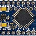
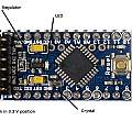
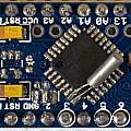
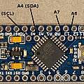
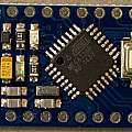
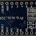
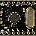
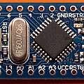
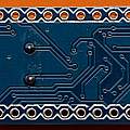
Click to enlarge photos. First one shows original Pro Mini, second with annotation, third modified Pro Mini with added clock crystal
I found ready to run software in the form of Asynchronous timer example by Nick Gammon. All I had to do was change
const byte tick = 3;
to
const byte tick = 13;
so it flashed the onboard LED.
Everything worked and I had a Pro Mini running on 1 microamp with an accurate clock. The maximum sleep time is 8 seconds, which is the same as using the built in watchdog timer (see Sensor). An alternative is to use a Real Time Clock chip (see Logger). Waking every 8 seconds does have a power cost see Waking from sleep mode.
How accurate is it? I set up code on the Arduino to print a character to the serial port every 8 seconds and then compared results to the clock on a PC running a program watching the serial port. Initially I used the millisecond clock() function available to C programs on Windows, doubting that, I added code to look at an NTP server, in fact the Windows clock() value kept in sync with NTP. The Arduino consistently lost around 5 seconds a day. I expect to only reset crystal controlled clocks twice a year (when Summer and Winter time start) and for them to be accurate to around a minute over that time - an error of half a second a day. However quartz clocks vary in their accuracy, maybe this crystal came from a poor one.
The Windows console application for checking time accuracy can be downloaded from the following link.
- Archive of PC application code - this is a Microsoft VC++ 6.0 project folder (23rd December 2014).
In passing when my PC is powered up the clock keeps excellent time, but the battery powered clock used the rest of the time loses a second or so per day. It appears Windows only synchronises time with the Net every few days. time.is is a simple way of investigating this behaviour.
If longer delays than 8 seconds between activity are required then a number of 8 second periods have to be chained together. This is not trivial. Problems can include, sleep mode terminating immediately a number of times before success and the processor using more power than desired when sleeping.
I found some material on a different technique (to the counter clear one of Nick Gammon referenced above) waking using counter two overflow, and pointing out the potential problems in chaining events.
I finally produced the code below, this can use either CTC (counter clear) or overflow mode, it chains events to give any desired period (greater than 1/32 second), and given some calibration information it corrects the timing of events.
In 16000 seconds I found an error of 1095 ms (the Arduino was running fast so the actual time was 15998905 ms). From this I got the correction factor in the code of 6.8442e-5. (Because 16000/15998.905 is about 1.0000684421840119683190818371632 and the code removes the value of 1, in an attempt to store big numbers separate from little ones).
double corr_factor=6.8442e-5;
The variable
realtarget_period=(5*8*32);
sets the time period, here 40 seconds.
Just one of the defines:
#define OVERFLOWMODE 1#define CTCMODE 1
should be uncommented to set the mode of operation.
Correction is done at the level of 1/32 seconds, so one sees the error build up to around 30 ms and then jump back towards zero.
- Archive of Arduino code - (1st January 2015)
More about low power operation
The resistors at the left hand end of the Pro Mini are marked 87A = 787 Ω, 66A = 475 Ω and 16B = 1.43 KΩ. The regulator is marked KBAA which is a Micrel MIC5205 adjustable voltage regulator (new Microchip datasheet). The output voltage is quoted as 1.242 (R2/R1+1) where R1 goes to Vout. Using R2=1430 and R1=475 gives a value of 4.98. Using R2=1430 and R1=787 gives 3.5. Presumably these resistors are connected via the 3.3/5 V adjustable link to select 5 or 3.3 V operation. This potential divider is connected across the power lines and results in a substantial current waste; so both sides of the link must be open for low power use.
Breaking a single track which on some other Pro Mini boards (see Logger) is all that is needed for low power use, results in the Vcc pin on the six pin USB/serial connector no longer supplying power to the ATMega, but still powering the power LED. Attaching power to the the Vcc pin on the long side of the board then gives ATMega operation but with the power LED dimly lit. To achieve correct low power operation I had to break two more tracks; first on the back of the board connecting Vcc to the resistor marked 66A; second on the top of the board connecting the six pin Vcc to the power LED; finally a wire jumper was soldered between the pull up pads (see next paragraph) and the six pin Vcc.
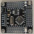
A technique that will work on any board is to remove the voltage regulator and either the power LED or the resistor feeding it. The simplest way of changing the crystal is to get a board with a full size crystal (see photos below); on these boards unsoldering the existing crystal and inserting a new one is easy.
It is possible to achieve low current use without removing the regulator - it depends on the regulator and Pro Minis are supplied with lots of different ones. Powering the Pro Mini from the Vcc pin it is the regulators reverse current that matters. There's another situation where you're connecting 3.3 V peripherals to the Pro Mini and actually need a regulator - some have very low quiescent currents with others the minimum current will be above 2 mA. A regulator with low reverse current is the Micrel (now Microchip) MIC5225.
Reducing the processor clock speed and voltage will save power - so an 8 MHz 3.3V Pro Mini uses much less current than a 16 MHz 5V version.
The Arduino Pro Mini design originated with sparkfun around 2009; the original version was enhanced; the new version featuring a jumper (SJ1) to allow low power operation and four pads to which I2C pull up resistors could be soldered. The versions from China (like the one above) seem to have copied the pull up pads but not the low power jumper.
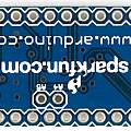
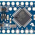
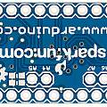
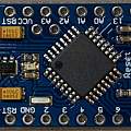
The next four photographs from sparkfun are reproduced under CC BY-NC-SA 3.0.
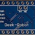
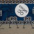
Click to enlarge photos. The first two are of the original design and the last two of the newer one. The extra solder pads are visible to the left of the A4 and A5 holes in photo 4 (Vcc going to the left hand pair and the right hand pair connecting to A4 (SDA) and A5 (SCL)). SJ1 is just above GND on the bottom row of holes in photo 3
Photos 1 and 2 show another popular design 'Deek-Robot'. The connector for the USB to TTL interface is reversed on the Deek-Robot board. The component marked T4 at the left is (see The SMD Codebook) an 1N4148 diode giving reverse polarity protection for Vcc on the six pin USB serial connector (and a 0.6 V drop); the one marked KB50 (not K850) is the fixed 5 V version of the Micrel MIC5205 voltage regulator. Photos 3 and 4 show the design used at the start of this page with annotation of the A4, A5, A6 and A7 holes.
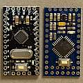
Photos of another two designs - both 5 V 16 MHz. Photo 1 compares them. Photos 2 and 3 are of one design. Photos 4 and 5 of the other.
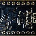
The last two photos are of the Baite board. A useful diagram of the internal wiring can be found here. From this diagram cutting tracks to achieve low power is a lost cause. I followed my advice above and removed the regulator and the power LED being careful with the latter to not break the ground connection to which the LED joins. Replacing the crystal was so easy I did it four times... The first 32768 Hz crystal didn't work - maybe a dud, maybe I overheated it during soldering.
Bricked
Having changed the fuses, and inserted a working 32768 Hz crystal on the Baite board, I found that programming via the serial interface did not work. I guessed this was due to the boot loader being set up for 16 MHz (compared with the 8 MHz internal clock). I burned in a new boot loader, at which point the board stopped working - bricked. It turns out that the Arduino environment resets the fuses when a new boot loader is programmed. Putting the 16 MHz crystal back restored operation, allowing me to burn an 8 MHz boot loader, change the fuses and install the clock crystal again. After which serial programming also worked.
Yet another design. The USB serial connector is the wrong way around again. The diode marked S4 apparently offering reverse polarity protection on the RAW pin.
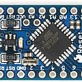
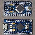
There is a "Pro Micro", this uses the ATmega 32u4 processor. Chief feature is built in USB, but there are others like differential ADC. The pin pitch on the processor is too small for easy soldering. The photo shows a Pro Mini and a Pro Micro.
Pro Mini Strong
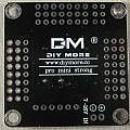
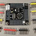
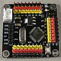
Usually sold as "Atmega328 Board 14 Pins Pincompatible For Arduino Pro Mini", "14" is the key search term (or try "strong"). This has S, V and G pins for each Pro Mini pin, those being Signal, Vcc and Ground along with an ICSP six pin programming socket. The SVG pins would be ideal for plugging switch type sensors into. There is a chunky AMS1117 regulator and a reverse polarity protection diode on the serial port Vcc pin.
References
Selecting and testing 32kHz crystal oscillators for Atmel AVR microcontrollers
ARDUINO LOW POWER - HOW TO RUN ATMEGA328P FOR A YEAR ON COIN CELL BATTERY
Russian database of SMD marks
Comments
Bhargav
My question was, along with normal crystal (8/16 MHz) do we need to remove both the capacitors attached with it?
I say yes, remove the capacitors, on some of my conversions I have simply broken the tracks between the ATMega and the existing components and soldered the crystal to the chip.
There is an Atmel/Microchip application note AN2648 about using clock crystals and you can see in the pictures there are no external capacitors.
Better answer - see section 12.4. "Low Frequency Crystal Oscillator" in the ATmega 328 datasheet which explains about the capacitors.
David Pilling's Wiki
Set view
