Started 4th February 2018
Experiences with the Bosch BNO 055 IMU - a combined accelerometer, magnetometer and gyroscope with a built in ARM processor that performs sensor fusion calculations.
I set off with the Adafruit BNO 055 board with the aim of connecting it to the Raspberry Pi. The first idea was to use the Pi serial port, setting it up looked complicated and I could not get it to work on my Pi mk 3. So next move, connect using I2C - that did work, but the data was glitched.
Research showed that the glitched data is due to the Pi I2C interface not supporting "clock stretching", there are various suggestions around along the lines of slowing down the Pi I2C clock, but I found no proper fix.
I then found a webpage [3] explaining how to set up the serial port on the Pi mk 3 and succeeded in getting connectivity to the BNO to work perfectly.
Moral - don't waste time on I2C on the Pi.
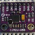
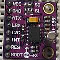
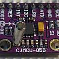
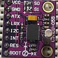
I then moved on to what might be called a "Chinese" BNO breakout board off ebay CJMCU-055. I could not get it to work with the Pi and moved to Arduino. Usually one can find schematics for such boards, but on this occasion documentation is very limited [1].
However the board sticks closely to the Bosch datasheet circuit [5]. There are three 10KΩ resistors connecting SDA, SCL and (not)Reset to Vcc. There are two solder pads for PS0 and PS1 which have to be bridged to either + or - pads to set the operating mode - I2C, UART serial etc. For I2C both are bridged to -.
The ATX pin is SDA, and the LRX pin SCL.
The only catch is the pin marked I2C which is connected to nothing other than the BNO055 and has to be grounded for the standard I2C address to apply. The marking on the back of the board for this pin "COM3" relates it to the datasheet.
There is a zero Ohm resistor which appears could be removed to split the sensor and processor power supplies.
Often these boards are supplied with a 32 KHz clock crystal which can be soldered to the board as shown.
Having got the board working in I2C mode on Arduino with the Arduino Adafruit library I tried again on the Pi and had to disconnect the reset pin to get this board to work on the Pi with the Adafruit Pi Python library.
The next problem was that (it appears - see the postscript below) the BNO 055 does not reload magnetometer calibration data, so the idea was to keep the BNO in suspend mode; according to the datasheet current in this is 40 μA. With the Adafruit board I found current of 200 μA and with the Chinese one over 300 μA. I pulled both boards to bits hoping to find some component using the extra current but with no luck. I would have expected the Adafruit board to use more current because it has a voltage regulator; but it turns out the regulator is an extremely low current model.
I emailed Bosch and to their credit they answered and said in their experience the BNO 055 could operate on 35 μA.
(Postscript - September 2019 Bosch also told me "measure the current in the ground line", a comment I did not understand and poked fun at - I was thinking of the breakout board where it does not matter how the current is measured. In 2019 someone got in touch and said they had disconnected the GNDIO pins to get much lower current use. This appears to be the solution to the low current problem. There's a GND pin and GNDIO pins.)
The Adafruit Arduino library allows:
Adafruit_BNO055::adafruit_bno055_rev_info_t data;
 bno.getRevInfo(&data);
  pr("revisions acc %d madg %d gyro %d sw %d bl %d",data.accel_rev,data.mag_rev,data.gyro_rev,data.sw_rev,data.bl_rev);
For the Chinese board I got 251,50,15,776,21 and for the Adafruit 251,50,15,785,21, the difference is in the software version 0.3.0.8 (776) against 0.3.0.11 (785). Adafruit obviously using the latest part.
Arduino version of the Bosch BNO055 library
Bosch do their own C library for the BNO, below is a port of it to the Arduino. This is simple, requiring some new type definitions in the .c file and three routines in the Arduino code (for reading and writing to I2C and time delays). I ported this due to problems with the other libraries - Bosch seem to know more about the insides of the BNO.
Postscript - June 2018, my feeling now is that the readable magnetometer calibration data is only updated on mode switch and some of the libraries don't do this correctly and that may be why it appears not possible to save and reload it. Having gone to great lengths to keep the BNO continuously powered and preserve calibration I found that the continuously running automatic calibration is likely to change results. In other words, "level" one day may not be "level" the next even though the sensor has returned to the same orientation.
The Adafruit forum has a discussion which covers some of the problems and limitations of the BNO 055. I could have saved myself a lot of time by reading this and believing it, because eventually I came to the same conclusions.
I abandoned the BNO 055 and moved to using the Hillcrest Labs FSM300 board which contains the BNO 080, the same Bosch hardware as the BNO 055 but with different on-board software. The FSM works well, but the fact that it exists points to problems with the Bosch version.
Possibly Bosch will fix things one day and make the above information obsolete.
Postscript - March 2023, someone pointed out the BNO 085 in Adafruit form here, things move on and improve.
References:
- CJMCU-BNO055与Arduino配合使用注意事项 (Precautions for use with CJMCU-BNO055 and Arduino)
- Adafruit BNO055 Absolute Orientation Sensor with Raspberry Pi & BeagleBone Black - Pi version
- Configuring The GPIO Serial Port On Raspbian Jessie Including Pi 3
- Adafruit BNO055 Absolute Orientation Sensor - Arduino version
- BNO055 Bosch home page for the BNO055, includes datasheet


