Started 27th June 2018
So you buy a CNC shield for the Arduino Nano off Ali Express marked Keyes-CNC 14/07/01 and it looks a nice colourful pcb but it won't work with GRBL.
This link suggests why. To explain a bit, the pins connected to the step and direction inputs to the motor drivers are swopped relative to the usual GRBL definitions.
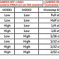
Secondly the jumpers to configure the number of micro-steps (in the middle of the motor driver sockets) connect the driver micro-step pins to ground when they should connect them to the logic high voltage (with no connection they default low). The result is the micro-step jumpers have no effect; the micro-step value is fixed at all zeros - maximum step size.
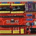
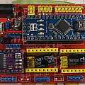
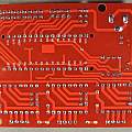
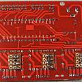
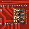
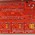
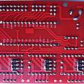
Photos show the top of the board, bottom and modification to make the micro-step jumpers work. The board can either drive the motors using power coming in via the barrel jack (as in the first photo, add the Mot-Vot-Sel jumper, middle far right) or via soldered connections on the top edge of the board (omit the Mot-Vot-Sel jumper).
I fixed the micro-step problem by soldering small bits of protoboard on to the leads protruding from the board with 10 or 12 KΩ SMD resistors which take the micro-step pins high when no jumper is present - the effect of these is to reverse the behaviour on other boards, here omitting a jumper produces a high logic value; for example no jumpers sets all ones which is 16 (A4988) or 32 (DRV8825) micro-steps - but at least the jumpers do work.
The pin at the bottom which is logic high is connected to the left end of the SMD resistors and the other ends to the micro-step pins.
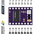
The orientation of the DRV8825 in the photo is correct (unlike some of the photos on the web), for an A4988 the pot would be at the other end of the board. For the DRV8825 the enable pin is on the corner next to the pot.
The micro-step jumper closest to the Nano is M2; the jumper for M1 is in the middle and M0 is closest to the edge of the board with the motor connectors.
Over at GRBL, the correct definitions in cpu_map/cpu_map_atmega328p.h are as follows, the comments show the original definitions. So originally X_STEP_BIT was 2, but for this board it has to be 5.
#define X_STEP_BIT      5  // Uno Digital Pin 2
#define Y_STEP_BIT      6  // Uno Digital Pin 3
#define Z_STEP_BIT      7  // Uno Digital Pin 4


#define X_DIRECTION_BIT   2  // Uno Digital Pin 5
#define Y_DIRECTION_BIT   3  // Uno Digital Pin 6
#define Z_DIRECTION_BIT   4  // Uno Digital Pin 7
Comments
Yahia (18th December 2023)
It is easier and cleaner to solder the smd resistors directly over the tracks since they are protected by the red soldermask (but an additional piece of the high temperature tape stuck under won’t be superfluous); here are some images, may you want to update the page.
