Started August 2024
There are "adapter plates" for the ESP32 akin to those for the ESP 8266.
The pitch is finer 1.27 mm (0.05") and soldering is harder. I found soldering one corner and then moving the module till all the pins line up worked, however getting three sides to line up over all the pins is non-trivial. For example an error of 0.005" (0.1 mm) on one pin will result in being a whole pin out over the length of the board. The pins are too dense to solder individually, drag soldering works, but means the solder free gaps in board and module must align. I messed up one adaptor and ESP32 attempting to clamp the ESP32 and adaptor together.
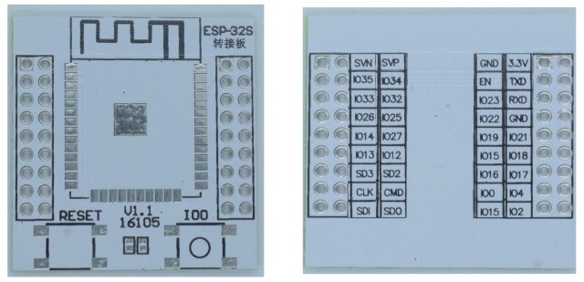
The first graphic is helpful because it shows (on the right) the names of the connections on the left. On the real world board the names of the connections are printed on one side but this is not so useful when you're looking at the other side of the board - you need a mirror image and that is what the graphic provides.
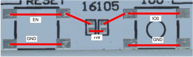
The second graphic explains the connections. The idea is to have a couple of resistors between the pads in the middle of the board. These would hold EN and IO0 high - pressing the switches then takes these pins low and either resets (EN) or puts the processor into programming mode (EN plus IO0). The switches join their top two pins to the bottom two when pressed. The resistors would run up/down.
There is a reference design for ESP32 boards on Espressif's web site here along with a schematic here. These show that the switches should be connected in parallel with capacitors to suppress noise. There is no provision for these on the board - IO0 is also not held high, because it has an internal pull-up. The adapter board is not as good as it could be.
I added capacitors across the switches, and then realised it was better to add things to the circuit the adapter plugs in to, because if a replacement adapter is needed there is no duplication of components. I failed to solder resistors to the adapter board, not enough metal to solder to is my excuse. Solder paste and reflow soldering would be more likely to work.
I programmed the ESP32 once using the switches, after that I added the usual pair of transistors to map RTS and DTR from the USB interface (FTDI etc.) to IO0 and EN (see the ESP schematic).
Photo 1 below is the bottom of the adapter board viewed from below, compare with the mirror image bottom viewed from above in photo 2.
Click to expand
