ESP
Started August 2015
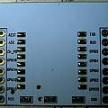
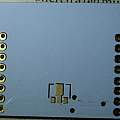
Later ESP 8266 boards break out more pins but do so on a 2 mm matrix. One ends up buying "Adapter Board for ESP8266" or "adapter plate" to convert to a 0.1 inch (2.54 mm) matrix. (See also ESP32).
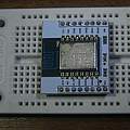
The example below has a few snags, it is so big it leaves no sockets on a standard bread board. The answer to this can be found on the Digits Domotica Blog (broken link, use Internet Archive version) - use long header pins. I used the headers supplied before discovering the problem.
The three resistors on the board are 10K, zero and 10K. The idea of the zero Ohm resistor is that one can optionally solder a regulator on the back of the adapter and remove the resistor, with no regulator present the resistor passes power along. One 10K resistor keeps CH_PD high, the other holds GPIO15 low. GPIO 4 and 5 appear to be marked in the right order (but possibly different to what is marked on the ESP board).
Useful pin information
GPIO pins 15-0-2 = 001 used for programming memory = 011 run code
REST =0 reset =1 normal
CH_PD =0 disabled =1 enabled
ESP8266 links
Kolban’s book on the ESP8266
espressif
Electrodragon firmware
esp8266-wiki
ESP8266 Community Forum
Arduino ESP8266
ESP8266 powered web server
Webserver under FreeRTOS on an ESP8266
ESP8266 BOOT PROCESS
https://primalcortex.wordpress.com/2014/12/30/esp8266-nodemcu-and-lua-language-and-some-arduino-issues/
http://www.esp8266.com/viewtopic.php?f=21&t=1710&sid=11a177505db3aeaf6bc6730a91bd8be9&start=10
David Pilling's Wiki
Set view


