I played with a few projects that involved calibrating clocks and eventually picked up [1][2][3] that GPS systems have very accurate pulse per second outputs (PPS). The advantage is that calibration can be done in seconds rather than waiting for hours.
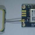
I got a UBLOX Neo 7M GPS board from ebay. The first thing I did was connect it to Windows using a serial to USB converter (FTDI etc) and use the free UBLOX UCENTER software. I was impressed that it located itself on Google earth within a foot or two whilst sat on my desk indoors. For such a small outlay (£8) one gets a lot of technology - free replacement satellites etc.
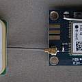
The PPS output is not available on the board connectors, but it is easy to add a wire from the signal line driving the LED on the board. First photo shows the supplied board, second with added 90° header with PPS output, click to enlarge.
My first effort at using the PPS output consisted of connecting it to an Arduino interrupt (pin 2 or 3) and recording the values of micros() in the interrupt handler which was set up to be triggered by a positive going transition. I printed out the time difference between events - expected to be 1 million. This simple approach did work but mixed in with the majority of correct values were quite a lot of wrong ones. The micros() time resolution is only 4 μs anyway [5] but it appeared to occasionally lose a few 100 μs between events - presumably as a result of other interrupts like the serial port.
- Archive of Arduino code for interrupt version - (26th August 2015)
I then found a good snippet of code [6] which uses the capture register in the ATMega [7][8]. A transition on Pin 8 saves the state of timer 1 to a special register and generates an interrupt. This gives much cleaner and stable results. It's good fun to warm the Arduino with a finger and see the small variation in clock speed.
- Archive of Arduino code for capture version - (26th August 2015)
As well as the GPS I also have some DS3231 Real Time Clock boards the time keeping of which is of interest. These RTC boards can be set up to output a 1 Hz square wave. What I wanted was to display the time in microseconds between the GPS and RTC PPS - measure the time between two edges. In time gone by one would have generated a difference pulse using logic gates, here in the 21st century I have a lot more computers to hand than flip flop chips. It is possible to trigger the capture register in the ATMega 328 using the output of the analogue comparator. The ATMega 328 has a built in comparator. One input of the comparator is taken from the internal voltage reference, and the other from the ATMega 328 analogue input multiplexer. The code sees a rising edge on analogue input 0 then switches the multiplexer to analogue input 1 and waits for another rising edge, printing out the time in microseconds between them. It then switches back to look at analogue input 0. Digital signal levels are being used on these analogue inputs.
Presumably this only works if the time difference between the two 1 Hz rising edges is big enough - what are the odds of that happening - high - assuming the minimum time difference is 10 μs - then about 99.999%
- Archive of Arduino code for dual capture version - (26th August 2015)
Using this display it is simple to tweek the aging register in the DS3231 to make its clock keep pace with the GPS. See my Logger page for the problems associated with cheap DS3231 boards from ebay.
Continued on Checking the accuracy of analogue Quartz clocks.
References
- High accuracy PIC timing systems
- Raspberry Pi Stratum 1 NTP server with PPS
- The Raspberry Pi as a Stratum-1 NTP Server
- Connecting u-blox NEO-6M GPS to Arduino
- Examination of the Arduino micros() Function
- Capture Facility of Timer1 - afremont
- Timers
- ATmega328P home page
- Input compare triggered analog compare
- Input capture analog comparator
- AVR Input Capture for multiple inputs
- Poor Man's Tiny Tuner tune Arduino clock speed
- Cascading Timers to Create a Long Delay
- AVR 133: Long Delay Generation Using the AVR Microcontroller

