Started 27th June 2017
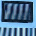
The idea is to print a fine grid, or mesh, or sieve. Typically a 3D printer has a 0.4 mm nozzle, one would like to print 0.4 mm lines with a 0.4 mm spacing. The problem is usually one does not have direct control over the printer output, things are designed and then sliced.
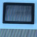
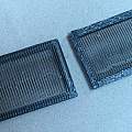
Using Cura 2.5.0 I found [1] that if the line size is slightly bigger than the nozzle size (0.41 mm as against 0.4 mm) then a single line results.
For the example I had the first layer height and the layer height as 0.28 mm, the frame is 1.4 mm thick and the single lines are 0.28 mm high.
Also shown in the pictures is some 0.4 mm line and gap printing from my 1200 dpi laser printer.
I had visions of producing these prints by writing gcode and I found a couple of interesting things. Firstly when the layer height is (say) 0.28 mm the gcode instructs the printer to move to Z = 0.28 mm for the first layer. Conclusion is that when the Z axis is homed there should be a zero gap between the nozzle and the bed. For calibration one can issue a G0 Z0.2 command and then check that the nozzle is 0.2 mm off the bed.
Secondly how the print parameters work - the assumption is that with a 0.4 mm nozzle one is drawing a line 0.4 mm wide, the rate of extrusion then controls the thickness (or height) of the line.
The following are a couple of consecutive lines from the g-code from Cura for this example.
G1 X115.999 Y103.553 E34.89188
G1 X115.999 Y104.119 E34.921
` Delta X = 0\ Delta Y = 0.566\ Delta E = 0.02912 `
To draw a line ` 0.566\ mm ` long with a layer height of ` 0.28\ mm` then ` 0.02912\ mm ` of filament is extruded, using a ` 0.4\ mm` nozzle and ` 1.75\ mm` diameter filament.
The volume of filament is ` pi xx (1.75/2)^2 xx 0.02912\ = 0.07\ mm^3`
The volume of the line is ` 0.566 xx 0.28 xx 0.4\ = 0.063 \ mm^3`


