HC-SR04
Started December 16th 2015
For schematics see (external links) Making a better HC-SR04 Echo Locator and Circuit Diagram Ultrasonic Distance Sensor HC-SR04.
Other relevant pages JSN-SR04T, Ringing.
A new development is the HCSR04 P variant.
I built a liquid level sensor using a capacitive sensor to monitor the water level in the crawl space under my house. This type of sensor did not work perfectly with the dirty water, eventually I replaced it with an ultrasonic ranging module, the HC-SR04. I am interested in a sensor to target distance around 100 mm and changes of that distance always less than 25 mm. Possibly that is unusual for a user of the HC-SR04 and for depth of under floor water. My aim is a quick response to level changes and an accuracy of 1 mm.
The result of all this is that a modified HC-SR04 can measure tiny distances.
A newer project is a liquid level sensor using a laser time of flight sensor.
The liquid level sensor is built around a "bare bones Arduino", roughly equivalent to an Uno, Pro Mini or other ATMega 328p based Arduino, so that's the processor I have to work with.
The HC-SR04 is positioned looking down vertically at the floor/water - it fires a pulse of sound and waits for the echo. There's a lot of space around the sensor with nothing in it so there are no echoes from other objects.
There is a very good web page Making a better HC-SR04 Echo Locator which covers a great deal including limitations. To start with I'm repeating material from that page.
The usual claim vendors make for the HC-SR04 is an accuracy of 3 mm. There are various sources of errors:
- Use of the Arduino micros() function to measure microseconds (e.g. in the NewPing[2] library), this has a resolution of 4 μs.
- The processor in the HC-SR04 polls the analogue electronics.
- The HC-SR04 is triggered by the amplitude of the pulse coming back, making no allowance for the phase of echoes or lost ones.
Monotonicity turns out to be a big problem - as the target distance increases the HC-SR04 output does not always increase. In other words the output is not a monotonic function of distance.
Given the speed of sound is 340 ms−1, sound takes roughly 3 μs per millimetre; double that to allow for going there and back. The wavelength of 40 kHz is 8.5 mm. The period is 25 μs.
For my liquid level sensor arrangement the front of the HC-SR04 is 75 mm from the ground, giving an expected time of 441 μs. Typically the NewPing library gives 415 or 419 μs; (it subtracts 5 μs from the micros() time - if you're worried about getting a multiple of 4 μs). A missed pulse would be expected to give an error of 25 μs.
A run of 14697 readings taken at 150 ms intervals gave:
value in μs (number)
447 (16)
451 (111)
455 (4639)
459 (7685)
463 (2119)
467 (124)
471 (3)
One simple improvement is to use the capture register in the ATMega[6][8] (see also GPS); a transition on Pin 8 saves the state of timer 1 to a special register and (optionally) generates an interrupt. This offers a time resolution of 1 μs (or less) as well as avoiding errors caused by other interrupts.
Using the capture register a run of 16268 readings at 150 ms intervals gave:
value in μs (number)
456 (1288)
457 (320)
483 (12345)
484 (2315)
Which look more accurate but seem to be in two groups 25 μs apart.
Download
- Archive of Arduino code for capture register version - (30th December 2015)
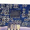
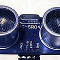
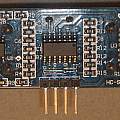
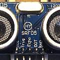
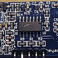
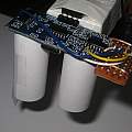
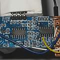
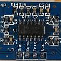
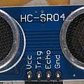
Photos 1 and 2 show the HC-SR04 module I used. The chip on the left is a SGM324YS14 quad op-amp, not the LM324 in some versions. This change is claimed to allow operation down to 3.3 V supply and lowers the current requirement (see below). The other two chips have no markings. Photo 3 shows an example of another "HC-SR04", this one does have an LM324 but is quite a bit different; for one thing the two transistors are missing. In [1] it is described how a MAX232 chip is used to drive the transmitter transducer; the idea is that it generates voltages outside the power supply range. I could find no such voltages. [24] claims the MAX232 is not powered on long enough to do anything (see the "postscript"). Photos 4 and 5 show the HY-SRF05 [13], a similar module. [26] looks inside the transducers.
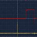
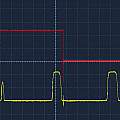
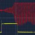
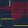
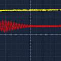
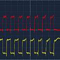
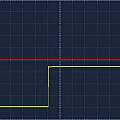
There are four pins, power (gnd and Vcc), echo and trigger. A negative going pulse on the trigger pin sets off a measurement. The echo pin then goes high for a time equal to how long it takes the sound pulse to come back. The first screen shot shows this, the echo pin pulse is red, and the trigger pin pulse yellow (hard to see because it is narrow and on the screen centre line).
The HC-SR04 analogue side consists of an amplifier, a filter, another amplifier and finally a comparator with hysteresis. The comparator has a 'threshold' input; the idea is that the comparator is turned off using this whilst the sound pulse is transmitted (see later). A sound pulse consists of 8 cycles of 40 kHz.
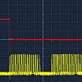
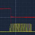
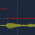
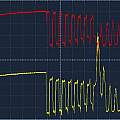
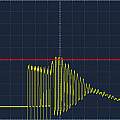
Using the circuit diagram in [1] it is easy to get the analogue echo data from the HC-SR04 analogue electronics by connecting to the collector of Q1 - this is the comparator output and it is what the HC-SR04 processor is connected to. The screen shot shows the result; red is again the signal on the echo pin; yellow the comparator output. It can be seen that the echo pin goes low when the first comparator output peak is received.
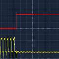
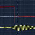
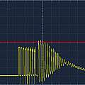
A couple more examples which show the first peak can be missed.
Looking at the comparator output I thought a lot more than 8 pulses were being sent. This is a screen shot of the signal sent to the transmitting ultrasonic transducer (yellow) and as before the echo pin (red). Apparently the echo pin goes high as soon as the last cycle is complete. There are two phases of the signal driving the transducer, the other one lines up exactly with the echo pin going high.
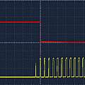
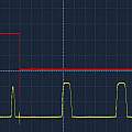
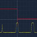
The comparator output traces in these screen shots show many cycles - not just eight. You might say multiple echoes; but the cycles are even (see Ringing). The simple idea is that as the distance between the HC-SR04 and the surface becomes smaller the comparator output data will smoothly shift to the left. This does not happen. As the distance decreases the first comparator output peak becomes smaller and eventually the processor misses it and jumps back to the next peak. The result is that decreasing the distance by a small amount can end up with the value returned by the HC-SR04 increasing (this is the lack of monotonicity).
These screen shots show this effect and also that the HC-SR04 echo pin output does not always line up with the same point in the comparator output data. Perhaps this is what [1] means by accuracy being limited by the processor polling.
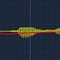
Thinking that the comparator with threshold input was hiding what was actually going on, I connected to the last amplifier output and got these traces. As before echo pin in red, amplifier output in yellow.
This screen shot shows the threshold input to the comparator in red and the final amplifier output in yellow. The amplifier output centres on 2.4 V - no surprise the amplifiers are biased to half the supply voltage. Similarly the amplifier output oscillations have a frequency of 40 kHz. The threshold minimum is 1.4 V and coincides with the start of the echo pin pulse; the threshold maximum is 2.4 V. The amplifier output positive peaks clip at 3.4 V.
The threshold signal goes to the inverting input on the op-amp used as part of a comparator and the final amplifier output to the non-inverting input. Q1 (the other part of the comparator) then inverts the op-amp output. As a result when the final amplifier output is less than the threshold the comparator output will go positive.
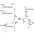
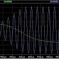
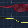
The comparator looking at negative peaks can only be accurate to the distance between peaks. An improvement is to add an envelope detector followed by a low pass filter. The effect is to interpolate between the peaks. The input comes from the HC-SR04 final amplifier output. An Arduino digital pin is used to reset the circuit by charging the capacitor C1 before the echo pulse envelope appears. First picture circuit diagram; second simulated input and output (green) signals; third real result.
Download
Making use of the analogue voltages that can be extracted from the HC-SR04 my aim was to use the ATMega 328p, rather than attempting to re-inject data into the HC-SR04 or build more electronics. Hence the target for the envelope detector output is the ATMega 328p analogue comparator. The capture register is used for all timings.
One input to the analogue comparator (AIN0, digital pin 6) comes from a potentiometer which is used to set the trigger level; the other input comes from the ATMega analogue multiplexer. The multiplexer switches between two signals; first the echo pin on the HC-SR04 (analogue pin 0), I assume the rising edge of this is honest; second the output of the envelope detector circuit (analogue pin 1). The code waits for a rising edge on the echo pin, then switches to the envelope detector output and waits for it to fall below the trigger level, finally calculating the time between the two events.
The result is a value which does not jump around - as expected - there is not the situation of just missing one peak and waiting 25 μs for the next. But the value is not monotonic.
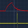
The next two screen shots show the final amplifier output (red) and a pulse (yellow) representing the echo time; the target distance is 1 mm greater in the first picture, but the yellow pulse is shorter. The problem seems to be that the echo signal interferes with a signal which travels direct from transmitter to receiver. In the second picture there is a discontinuity (white marker) where the two are out of phase and the overall amplitude is reduced. To put it another way amplitude depends on phase, as a result detecting echo time by amplitude gives incorrect results.
One way of reducing the direct signal is to add paper tubes to the HC-SR04 as shown in the first photo. The second photo shows how the voltages were extracted - going from left to right on the added piece of board on the right hand side - these are final amplifier output (white), T2 phase transmitter transducer drive (blue), comparator threshold (yellow), Q1 collector/comparator output (white). The other side of the added board has four right angle header pins.
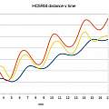
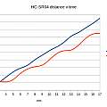
Graph shows time against distance, using the envelope detector with and without tubes and the standard HC-SR04 echo pin output. The time origin has been shifted to zero and the distance origin to 1. It can be seen that using tubes improves the lack of monotonicity and that there is a roughly 4 mm period to the deviation from a linear relationship between time and distance. To get the data I had a stack of 18 x 1 mm thick pieces of card, which I removed one at a time.
Download
- spreadsheet and data for above graph - (31st December 2015)
Whilst amplitude has problems, phase is beautifully sensitive to changes in distance - but there is only 2 pi's worth of range, or one wavelength, allowing for the trip back and forth this is about 4 mm. Using phase the HC-SR04 can reliably resolve distance changes less than 1 mm.
To get the Arduino to measure phase, the final amplifier output of the HC-SR04 is connected to analogue pin 2, and the analogue multiplexer switched to connect this pin to the comparator a short while after the envelope detector has seen the echo pulse. It turns out that the level of this signal allows a single value to be used on the other comparator input for both envelope and phase - just one pot to twiddle.
Download
- Archive of Arduino code for envelope/phase version - (1st January 2016)
It is possible to fit distance to be a function of time and phase. I got:
distance=0.145*(C+(time-562.5)) with C=19*sin((phase/25)*2*pi-0.25)
phase is in the range 0..24. This is accurate to about 1 mm. Of note is the value 0.145 which should be the speed of sound divided by 1000*2. The amplitude measurement might be sensitive to the reduction in amplitude with distance, but this can also happen if the sound travels at an angle (see below).
Another way of getting rid of the direct pulse from the transmitter to receiver transducer is to use another HC-SR04 as a transmitter only and place this second HC-SR04 some distance below (and behind) the first one (which is used as a receiver only). This works quite well and results become monotonic.
This screen shot shows the result of pointing the HC-SR04 into the void, no objects in range. Red is the final amplifier output, yellow the echo pin. Everything visible is the direct pulse from transmitter to receiver. At 200 μs per division, this lasts for 1.2 ms; one can observe that to get rid of this effect the sensor target distance has to be over 200 mm. Seeing this explains the time varying threshold used on the HC-SR04's comparator. Echoes from distant objects will return a voltage less than the direct signal, the HC-SR04 has to be able to detect them, but it must not trigger on the direct signal. The solution is a threshold which prevents triggering on low level signals until the direct pulse has decayed.
It is apparent that the receiver transducer takes time to start moving and then goes on oscillating for a long time (see Ringing). One idea was to short it out with a MOSFET long enough for the direct pulse to pass by. This was not a success, as soon as the MOSFET was turned off oscillation would start. However what does work is damping the receiver by putting some resistance in parallel with it. This can get rid of the direct pulse and allows more detail to be seen in echoes - because they don't last as long and no longer overlap. But it reduces signal levels and with the HC-SR04 measurements become noisier.
Given the success with two HC-SR04s providing a separate receiver (rx) and transmitter (tx) - I thought putting some distance between the transmitter and receiver transducers was the solution, to achieve this with a single HC-SR04 I un-soldered the transmitter and positioned it away from the receiver. The graph shows the results (orange) compared with using two separate modules (blue); the curve is just monotonic but not linear (still a lot better than the earlier graph from an unmodified HC-SR04). There has to be something to make the line wiggle - my guess is that having removed the direct signal through the air, there remains some electronic crosstalk between receiver and transmitter. It can be seen that good results are obtained using two HC-SR04s.
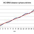
This graph shows both measured time and phase for the single HC-SR04 with un-soldered transmitter. Despite measured time wiggling, phase is linear. The phase is shown in units of 1/25 of a cycle (2 pi) (μs in other words). It is also shown in accumulated form; it's not possible to measure phase outside the range 0..2*pi for a single reading but with a series of measurements it can be determined where one cycle ends and the next begins.
One measure of sensitivity is how much measured time changes for a change in distance. Obviously
But that only holds if the sound travels at right angles to the target surface. If it travels at an angle the change in time for a given change in distance is diluted and the speed of sound calculated as above increases. Here the change in distance is perpendicular to the sensors - think rising water. There is an advantage in making the transducers transmit and receive sound perpendicular to the surface but that has to be done whilst making it difficult for sound to take the direct route between them.
The maximum rate of change of voltage output from the comparator is 5 mV per μs giving an error of 0.17 μs per mV error in the comparator trigger level. In practice a change of supply from 5 V to 4.5 V changed the echo time by 25 μs; the phase value did not change as the supply altered.
Current consumption was 20 mA, which can just be supplied by a single ATMega digital output pin.
Splitting the transmitter transducer from the rest of the HC-SR04 gives a way of measuring the distance between two points - simple time of flight, without the complications of echoes. No use for liquid depth unless one was prepared to float the transmitter.
I did consider generating the fixed ATMega analogue comparator voltage (the one supplied by a potentiometer above) from one of its PWM outputs, measuring the maximum of the envelope detector output and then measuring the echo time at various points; for example 50% of the maximum (by setting a suitable PWM output). This way one might be able to get rid of dependencies on supply voltage or non-monotonic behaviour. This is a variation on the idea of compensating for not having a fast analogue to digital converter by relying on the echo pulse being repeatable and measuring it many times.
Processors with fast analogue to digital conversion are cheap and there seems no point expending effort for the sake of times long past. My next project is to replace the processor with an STM32 - see STM32 with HC-SR04.
It turns out that the analogue to digital convertor in the 328p is fast enough - see part 2.
- Archive of Arduino sketchbook SensorTXUS - (31st January 2016)
This is the code for the ultrasonic version of the complete Sensor, including the radio, temperature/humidity and power saving code; the libraries are not included and can be found on the Sensor page.
What happened
It seems to work well, returning stable results and showing changes less than 1 mm. Given the water level usually moves very slowly the phase value can be used.
Second thoughts
A lot of web pages suggest a fast pulse is needed to trigger the HC-SR04 and I've copied that code. But it seems a slow negative transition will do. See the screen shot - 1ms per large division - red trigger, yellow echo pulse.
I've had no luck using 3.3 V to power the HC-SR04 regardless of the op-amp type. Other people seem to have had success. It also seems that some people have seen the MAX232 work as intended [25]. This and the above point to the variations in what an HC-SR04 consists of. I've not had one with a chip actually marked MAX232, and they could be simpler driver (buffer) chips (see the "postscript").
Instead of leaving well alone I continued to play with the ATMega and the HC-SR04 - see part 2.
Postscript - March 2018
The above might be read as if a HC-SR04 is a known quantity, in fact that's not the case. Two different versions of the HC-SR04 pcb are shown in the photos, the earlier two transistor version which is designed for a MAX232 chip and the later version which has a simple driver (buffer) chip. The schematic of this second version is available from another very good web page [27]. The HY-SRF05 appears to be similar to the older HC-SR04. My speculation is that the original HC-SR04 had the MAX232 chip, at some point this was replaced with a simple buffer chip (giving the version I had when I started), finally the now redundant components to support the MAX232 were removed from the design (i.e. the two transistors and a few capacitors) giving the later version. This explains why some people have seen the MAX232 chip work (produce drive voltages greater than 5V) and others have not.
Experiment #1
Buy a HY-SRF05 from a vendor who has a photo of it with a MAX232 visible. Result get a board with an unmarked chip which is not a MAX232 (proved by measuring drive signals to the transmit transducer)
Experiment #2
Replace the unmarked chip in an HY-SRF05 with a MAX232. Result it doesn't work. Why? Because the PNP transistor in the circuit has been replaced with an NPN (it is only necessary for a MAX232, so anything can be fitted for the simple buffer chip). The capacitors which surround the MAX232 appear to be "null capacitors" - values too small to measure.
I eventually replaced board (schematic [1]) identifiers Q1 (Q2) with a 2N3906, C1 (C16), C4(C17), C5(C14) C2(C15) and C3(C13) with 220 nF capacitors (I had no 150 nF to hand).
After that the board worked. The 'scope traces below show the drive signals to the transmit transducer of the unmodified board (2 V, 2 V and 20 μs) and the MAX232 modification (5 V, 5 V and 50 μs). One trace for each pin on the transmit transducer.
Postscript - December 2018
I learnt about the P version from [28], but it seems to have appeared in 2017. It is claimed to run from 3.3 V. Looking at the component side view, the chip in the middle is an LM324 quad op-amp, the right hand one (U2) is a micro-controller and the left hand one (U3) (RCW9006) a buffer. The transmit transducer is on the right hand side, as far from the drive signals as possible.
'Scope results, channel 1 and 2 1V per division, time 100 μs. In the first the red signal is the trigger input, and yellow the echo output. The transmit transducer is driven by anti-phase signals, call them P1 and P2. The hardware is running from 3.3 V and worked, it is apparent the amplitude of the transmit signal is limited to the supply voltage.
The microcontroller pins are, 1 +Ve, 2 threshold output, 3 Echo output, 4 trigger input, 5 P1 output, 6 received signal input, 7 P2 output, 8 -Ve.
The buffer pins are, 1 P1 input, 2 P2 input, 3 received signal in, 4 -Ve, 5 and 6 received signal output, 7 P2 output, 8 P1 output.
From this it looks like the circuit is close to [27].
- Making a better HC-SR04 Echo Locator
- NewPing Library for Arduino by Tim Eckehesl
- Temperature compensation for an Arduino ultrasonic distance sensor by Sverre Holm
- Better microsecond resolution than micros
- More precise micros function
- Timers and Counters - Nick Gammon
- Interfacing HC-SR04 ultrasonic sensor with AVR
- Capture Facility of Timer1 - afremont
- Ultrasonic Anemometer (Wind speed and direction)
- Time of flight difference in hardware
- Project#09 US-100 Ultrasonic sensor
- US-100 ULTRASONIC SENSOR MODULE
- Ultra cheap ultrasonics with the HY-SRF05
- US-100,SRF06
- Ultrasonic Sonar Module US-100
- SRF05 - Ultra-Sonic Ranger
- Raspberry Pi and monitoring sump pump water level
- Arduino: User Error -- AIN0 *IS NOT* A0
- Arduino / AVR Analog Comparator
- Using the Arduino Analog Comparator
- analogComp is a library to manage the integrated analog comparator of some Atmel MCUs
- Ultrasonic Anemometer
- Virtual touch screen (3D Ultrasonic Radar)
- Re: How to talk from one HC-SR04 ultrasonic sensor to another?
- Spread Spectrum Phased Array Sonar
- scanlime:011 / Ultrasonic Transducer
- Circuit Diagram Ultrasonic Distance Sensor HC-SR04
- Tooling Tuesday - HCSR04P Ultrasonic Sensor
- SRF04 - Ultra-Sonic Ranger is this where the HC-SR04 design originated.
David Pilling's Wiki
Set view
