Started 10th Feb 2020
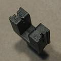
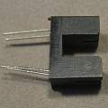
The ITR9606 is described by its makers as an "opto interrupter" (aka photo interrupter, slotted optical switch), the idea is common, a source of light (LED) and a light sensor (photo-transistor) separated by a gap which objects can pass through. When an object crosses the gap the output of the sensor will change. These are low cost components produced in big quantities and are found in many products.
My interest was how the output varied with the position of something blocking the gap. To measure this I suspended a metal blade below the print bed on my 3D printer and lowered it into an ITR9606. I used an 820 Ohm resistor for the LED side of the device and a 10K resistor for the transistor sensor side and powered everything from 5V. An Arduino Pro Mini was used to record the output voltage.
The position was varied in steps of 0.005 mm (5 microns or 5 μm). The printer has up to 1600 micro-steps per mm and 100 true steps per mm. The step of 0.005 mm is using the biggest micro-steps which are expected to be the most accurate micro-steps.
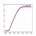
The graph shows a resolution of 0.005 mm is possible over a range of about 0.1 mm. This distance range corresponds to 5 V in other words a change in distance of 5 μm giving a change in voltage of 0.25 V.
I use this linear mode in an Opto position sensor.
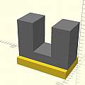
ITR 9606 3D OpenSCAD model and base holes
Download


