started 16th November 2016
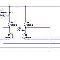
Back in 2014 I devised a circuit that automatically switched the power supply to a microcontroller depending on which of two sources had the highest voltage - see Power Oring. This circuit is more efficient than using a couple of diodes.
More recently I was wondering if a MOSFET could be used to replace the reverse protection diode in a solar powered project when I noticed [1] that 'ideal diodes' were available on ebay to do this job. An ideal diode has a much smaller forward voltage drop than a real diode.
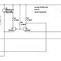
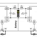
Eventually it occurred to me that my Power Oring circuit was equivalent to two ideal diodes. Perhaps it could be made to work as a single ideal diode. It turns out to be easy to do, simply remove one of the MOSFETs. But in this form the circuit is the same as the ideal diode described in [2].
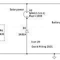
To help make sense of the circuits that follow, this is the equivalent using a normal diode.
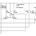
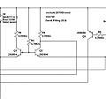
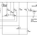
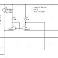
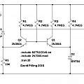
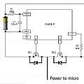
Graphics show first, Power Oring circuit. Second, result of removing one FET producing ideal diode. Third, adding an extra FET and transistor to allow solar power to be turned off. Fourth, often two FETs come in one package with a common drain. Fifth, I'd like the solar power to be on by default when the circuit powers up.
The ideal diode has a forward voltage drop of around 30 mV and a leakage current of 3 µA.
Postscript 2021
I found [3] a version that omits the common base resistor.
There are integrated versions "Synchronous rectifier diode DK5V45R10 DK5V45R15 DK5V45R20 DK5V45R25", "PN8306M consists of a synchronous rectification controller and an avalanche-rugged power MOSFET, specifically designed... to replace traditional rectifying Schottky diode".
My project has a micro-controller powered by a lithium battery; there's a solar panel which is supposed to charge the battery. The micro-controller can stand a varying supply voltage so there's no voltage regulator - which saves power.
The original idea was to rely on the protection chip built into many batteries. When the battery voltage gets too high this will stop any current flowing into the battery (but does allow current to flow out). When the voltage gets too low the reverse happens, current can flow into the battery but not out.
The micro-controller can monitor its power supply voltage and could decide when to disconnect the solar panel and stop any further charging. The third graphic above shows an extension of the circuit to allow this.
One possible situation is the battery running down and power to the micro-controller being turned off. It is desirable that the circuit then defaults to connecting the solar panel, allowing the battery to recharge and normal operation to continue.
The other unhappy situation is that the battery over-voltage protection activates and the no-load solar panel voltage is applied to the micro-controller (before it has chance to turn off the panel). My solution to this is a circuit that shunts the solar panel when the voltage gets too high. The difficulty is not wasting any power when the voltage is normal. I found a Zener diode did not switch between low and high currents fast enough as voltage varies, and adding an amplifier meant more leakage current. By experiment a 5.6 V Zener had very low leakage and the circuit below switches on a shunt device when the Zener starts to conduct.
In the circuit a 2N7002 is shown as the device used to conduct the excess power, but one would use something capable of handling more power.
All that seems a bit complicated - but has the advantage that the micro-controller can determine how the battery is charged.
The next idea was to retain the ideal diode circuit, get a battery with no built in protection and use a DW01 battery protection ic with the solar panel connected to one end and the battery the other. Over-voltage results in the panel being disconnected. The micro-controller can be powered from the middle of the circuit, but I decided to use a second DW01 to gain short-circuit and over-current protection.
References
