JSN-SR04T
Started 15th January 2021
See also Ringing and HCSR-04
As well as the common HCSR-04 ultrasonic ranging module (and variants) another one often seen on ebay etc is the JSN-SR04T-2.0. It has some interesting differences, it has just one transducer, it has a transformer to drive the transducer and the transducer is weatherproof. Documentation and a schematic exist.
There is a fine blog page about it:
HC-SR04 and JSN-SR04T-2.0 distance sensors, WOLFGANG EWALD
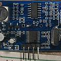
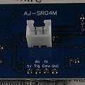
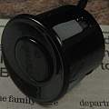
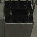
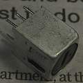
I bought one from AliExpress. Photos show the front and back of the board, the transducer and the transformer.
Ah wait a minute this is an AJ-SR04M. It is similar looking to the JSN-SR04T-2.0 but there are differences. There is also a JSN-SR04T (with out the 2.0) - both JSN versions are shown in [1]. Quick check the AJ-SR04M has an empty location for a resistor R19 (near the pins), the JSN-SR04T-2.0 labels it R27 and the JSN-SR04T does not have it.
The transformers are sold separately; the primary winding of the transformer has an inductance of 0.15mH and resistance of 3.3 Ω, the secondary 6.4mH and 16.9 Ω. Roughly a ratio of 1:6. The three pins mark the secondary side and the middle pin is not connected.
The basic interface is the same as the HCSR-04, four pins which are +5 V, GND, trigger and echo. A negative going pulse on the trigger pin input sets off a measurement. The echo pin output then goes high for a time equal to how long it takes the sound pulse to come back.
Given the speed of sound is 340 ms−1, sound takes roughly 3 μs per millimetre; double that to allow for going there and back. The wavelength of 40 kHz is 8.5 mm. The period is 25 μs.
The minimum distance that can be measured is 200 mm about 1200 μs.
The analogue electronics consist of an LM324 which contains four operational amplifiers. Three of them are used as amplifiers and filters, the final one is used as a comparator. The comparator compares the amplified signal with a reference voltage.
Unless stated otherwise voltages in the graphics below are relative to ground aka 0V.
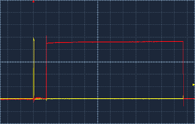
Standard operation. Yellow trace shows trigger pin signal, 1 V/div, 200μs/div. Red trace shows the echo pin signal, 1V/div. Duration of the echo is about 2200 μs or 366 mm.
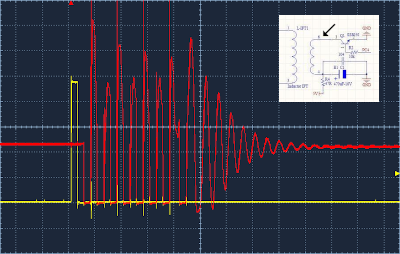
Transformer primary drive. Red trace 2 V/div and yellow trace 1 V/div both 50 μs/div. The yellow trace shows the trigger pin signal and the red trace the low side voltage of the transformer primary.

It is apparent there are 8 pulses, but the last of them is delayed by half the period to reduce the ring time.
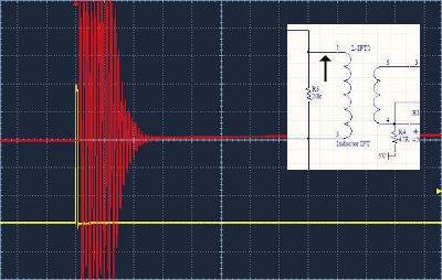
Transformer secondary high side. red 10 V, yellow 1 V 200μs, yellow trigger pin, red high side voltage of the transformer secondary.
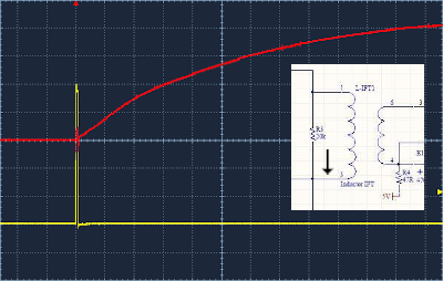
Transformer secondary low side. red 500 mV, yellow 1 V 200μs, yellow trigger, red low side voltage of the transformer secondary (see V/2 below).
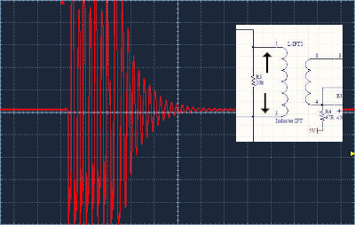
Transformer secondary differential voltage. red 10 V 100μs
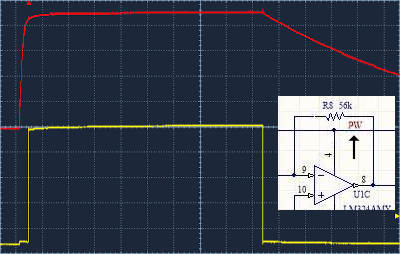
Pin 4. 1V 500μs, yellow echo pin, red pin 4. This is the line marked "PW", positive power to the four operational amplifiers.
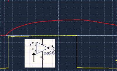
Pin 12. 1V 500μs, yellow echo pin, red pin 12. Pins 12, 10 and 5 are connected to a voltage that is half the positive rail voltage (call it V/2). It is used to bias the operational amplifier's non-inverting inputs. In many of the traces on this page the signal is superimposed on V/2. It would make more sense to measure signals relative to V/2.
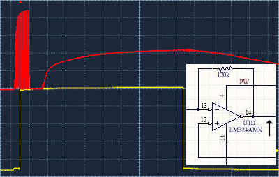
Pin 14. 1V 500μs, yellow echo pin, red pin 14. First amplifier output. The received echo signal is too small to see.
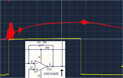
Pin 8. 1V 500μs, yellow echo pin, red pin 8. Second amplifier output; received echo signal now visible.
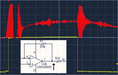
Pin 7. 1V 500μs, yellow echo pin, red pin 7. Third amplifier output.
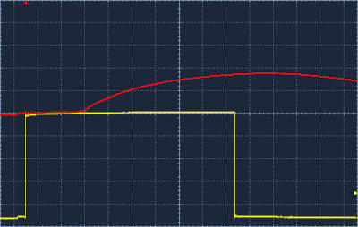
Pin 2. 1 V 500μs, yellow echo pin, red fixed comparator input relative to ground.
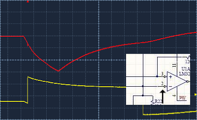
Pin 2. 500μs, yellow echo pin 1V, red fixed comparator input pin 2 relative to V/2 500 mV.
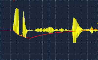
Pin 2 and 7. 1 V 500μs, yellow pin 7 final amplifier output, red fixed comparator input pin 2, both relative to V/2. When the yellow crosses the red an echo will have been received. Many stray echoes almost cause this to happen. It is apparent that the required strength of the echo to trigger the comparator is less as time goes on.
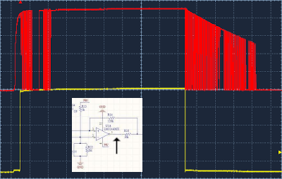
Pin 1. 1 V 500μs, yellow echo pin, red comparator output
The transformer not only steps up the drive voltage to the transducer, it also reduces the ringing time. With the module connected to a 'scope one can see the effect by twiddling the core in the transformer. If this is set wrongly the module won't work properly.
References:
David Pilling's Wiki
Set view
