Self Mixing Laser Diode Interferometer
Started 8th October 2020
See also: Laser Line, Copper Head Laser Diode
Ben Krasnow's excellent Applied Science You Tube channel has a video Laser diode self-mixing: Range-finding and sub-micron vibration measurement which offers a simple way of measuring changes in distance less than the wavelength of light.
Light from a laser-diode is reflected from the object of interest back into the laser-diode, interference makes its brightness change and this is measured using the built in photo-diode.
I tried to repeat the video but took a long time to get things working. At the end I found a simple and cheap way.
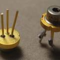
In the video there is the implication that three pin semiconductor lasers are going out of fashion. The three pins are a common connection, a laser-diode and a photo-diode which monitors the amount of light the laser produces. I bought some ADL-65055TL lasers from CPC (Premier Farnell), other large electronic distributors sell similar components, and they're available on ebay and AliExpress.
My idea was I'd power up the laser and, monitor the current through the photo-diode whilst reflecting the light from the object of interest and everything would work just like on YouTube. This did not happen, any signal was lost in noise, down among the millivolts.
One mistake I made was assuming that the interference between the light and reflected light takes place on the surface of the photo-diode. This made me try to hit the photo-diode with the reflected light and worry that the reflected light would need to have a similar amplitude to the transmitted light.
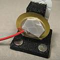
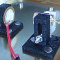
Although my object of interest has a shiny metal surface, lack of results made me follow the video and obtain some retro-reflective tape (3M Reflective tape ECE104). I made a more controllable target from a generic ebay piezo disc and I stuck some of the tape to it. I connected the piezo to my signal generator. The tape is obviously a good idea making directing the beam easier, but things still would not work.
In the video there's the statement that things will work without a lens, but most of the demonstration uses one. The output from the laser spreads a lot and it's nothing like a laser in the movies or even a laser pointer. Cue fruitless fiddling with lenses.
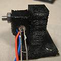
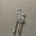
I eventually got a working set up by using the cheapest laser off ebay (see Copper head laser diode), these have a built in lens but no photo-diode. I pushed a photo-diode (PD204-6C) in the hole at the back.
Getting things to work requires the laser to be bright enough. The interference takes place in the laser diode and the photo-diode shows the resulting change in laser light output. The change in output is relatively small, say 1%, there's a large constant component.
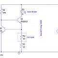
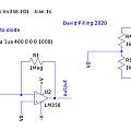
To drive the laser I built a simple constant current power supply. For the photo-diode I followed the video and common practice and built a transimpedance amplifier. This converts current to voltage. 1 μA in gives 1 V output (or whatever). I used an LM358, a cheap rail to rail dual operational amplifier.
There is an obvious problem and the video hints at it, if the constant current through the photo-diode is large enough the amplifier output voltage will reach the supply rail. In the video there's talk of using a couple of 9 V batteries - to get a big enough range.
My eventual success with the copper top laser and separate photo-diode was due to being able to run the laser at high brightness with not much light reaching the photo-diode.
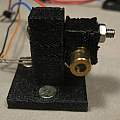
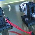
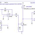
I produced a better circuit, a transimpedance amplifier with an integrator which subtracts the constant component of the laser diode output. Using this along with an ADL-65055TL mounted in the optics from a cheap Laser Line I got a strong signal, around 1 V.
The target and the laser are held by 3D printed bases which have three magnets in their bottom, allowing them to be stuck to a magnetic surface.
Note that although "Laser Line" is what they're commonly sold as, I used the version with a lens that produces a dot. I did not try the laser-diode in the laser line, I expect it would work, just disconnect the power control circuit.
Results
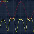
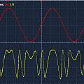
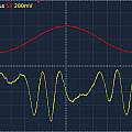
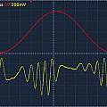
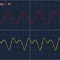
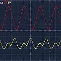
'scope screen shots at 200 Hz, 5 KHz and 40 KHz. The drive voltages (red trace) for both images of each set are 10 V and 20 V. The expectation is that more drive voltage will give more movement, and hence more changes of polarity (oscillations, or wiggles) in output (yellow trace). The most convincing thing is that the output is not at the input frequency.
Circuits
The simple constant current power supply for the laser diode.
Basic transimpedance amplifier.
Improved transimpedance amplifier which subtracts the constant component of the photo-diode current.
Download LT Spice files for all the circuits
Given the circuit is connected to the laser diode it could adjust the power output, rather than using a separate constant current supply which has to be set up by hand. Another approach would be to use the power control electronics from the line laser and connect them in place of the photo-diode in the circuit with constant current subtraction. Some adjustment of component values would be needed.
David Pilling's Wiki
Set view
