NiMH cell protection
I encountered the problem of packs of AA NiMH cells ending up with one cell with a voltage of zero or less. This first happened with my Wireless liquid level sensor. The problem is made worse by having a device which can run on low voltage and low current for long periods and is turned on all the time. In the pack one cell holds less charge than the others and is discharged completely first, and then reverse charged by its stronger companions.
In the world of Lithium batteries all this is common stuff. They have electronics built in to prevent over charging or discharging. Bottom and top balanced charging are different ways of approaching the problem. The DW01 is a common battery protection chip.
You could say if the sensor will work on 2 AA cells, why power it from 4 (originally) and from 3 (at the moment). This page will turn into a long argument for using a single lithium cell to run Arduino like projects.
One idea is for the sensor to look at the battery voltage when it wakes up and not transmit data if it is too low. I tried this and the current drain was still enough to reverse charge a cell. An improvement would be to put the sensor into sleep mode and turn off the wake up interrupts. The liquid level sensor draws 10's of μA when sleeping, my later sensors use a lot less.
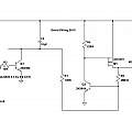
The idea then is to have the sensor monitor the battery voltage and when it gets too low turn itself off using hardware. The ideal circuit would turn on power to the sensor when the battery is first connected, have no losses, and when commanded, turn off the power and put the whole system in a state where no current flows (such an electromechanical device is called a latching relay). This is a bit like sawing off a tree branch while sitting on it (not as easy as it is reputed to be). This is my first attempt.
Click to view large version.
Current when in the off state is around 20 nA. I omitted Q1 and used an Arduino output pin. This was kept as an input until turning off the power was needed, when it was changed to a low value output.
if(vcc<33){ pinMode(SWITCH_PIN, OUTPUT); digitalWrite(SWITCH_PIN, LOW); return;}
C2 ensures that when power is applied the circuit turns on - at least if C2 is discharged - a momentary action switch could be connected across this to act as a reset. But in my usage, where the batteries will have been removed for charging, C2 will have self-discharged before they're replaced. C2 also ensures that a turn off signal will be extended in duration - so if the output pin starts to sink less current as the supply voltage falls, the circuit still turns off.
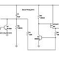
There's quite a bit wrong with this circuit. If C2 self discharges fast enough, the circuit will turn back on. In the power on state the circuit uses 20 μA - too much. To fix this I added another resistor and used 10 MΩ resistors throughout. Giving the second version below; which I built and added to the sensor.
Click to view large version.
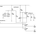
If one abandoned the auto power on feature, the discharged capacitor could be used to keep the power off, meaning it would not be connected across the power supply and there would be no worries about leakage current. An idea is to monitor the individual cell voltages and switch these at the same time as the main power; resulting in a circuit like this one.
Click to view large version.
This illustrates another issue, one uses analogue inputs to the MCU to check the battery voltage, but they will be protected with internal diodes, as soon as the power turns off the diodes will conduct, the circuit shows current limiting resistors and MOSFET switches which turn off when the power goes off.
Turning to a completely different approach. There is a simple circuit using one MOSFET to provide reverse polarity protection.
Click to view large version.
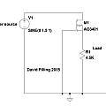
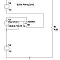
Thinking along these lines gives this circuit, when the cell voltage falls too low the MOSFET will cut off power. Problems here are the need for a low MOSFET threshold voltage (lower than the minimum battery voltage) and the (lack of) sharpness of the transition which might leave the MOSFET dissipating a lot of power. Notice the MOSFET is reversed compared to the reverse polarity protection circuit - as a result there is no reverse polarity protection. An AO3401 gives a voltage of 1.1 V and an AO3415 0.9 V. The graphic shows three cells in series with only the middle one protected, the emulation demonstrates the effect of the middle cell's voltage varying.
Click to view large version.
I've experienced the same problem of reverse charged cells with with commercial products - like my camera strobe (flash gun) which got accidentally turned on and left for a long time. Although MOSFETs are tiny, incorporating them into the battery holder or batteries is too intricate. My solution would be to put a micro-controller inside the device along with the last of the micro-controller circuits above.
References
EEVblog #262 - World's Simplest Soft Latching Power Switch Circuit
Simple Momentary Switch Latching Circuit - Circuit Salad
Improved Power Toggle Latching Circuit
Push Button ON/OFF Power Control Using MOSFETs
The push on push off transistor switch
Latching power switch uses momentary-action pushbutton
David Pilling's Wiki
Set view
