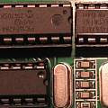
PIC Programming
Started 17th April 2022
The cheap K150 programmer does work with Windows 10 in 2022
I needed to program a PIC microcontroller (12F675). I bought "PIC K150 ICSP Programmer USB Automatic Programming Develop Microcontroller +USB ICSP cable".
Getting this and plugging it in to my Windows 10 PC the first problem I encountered was that it had a fake (or no longer supported) PL-2303 USB to serial adaptor. The solution to this is loading an old driver. I found [1] was a good implementation.
The first result on Google for software to control this programmer is microbrn.exe, a free download [4] [5], but something that has not been updated since 2007, from the supported PIC chips angle that's not a problem, but it is worrisome if it will run on modern Windows.
I struggled for a long time to get microbrn to work - even when this program works, it raises errors, so it is hard to decide if it is working or not. Maybe the USB driver was not functioning correctly. Seemingly the K150 design and software originated from a company called KitsRUs. The design of the K150 has evolved, various schematics are available [6].
"Why don't you just buy the proper programmer from Microchip" - because they're not offering delivery until July (months from now). I could buy a PicKit programmer off ebay, but those look to have similar fake chip issues. The Microchip software appears to be just under 1GB and I don't want the complexity of loading it on to my PC.
There is portable/open source software to control the K150 programmer [2] [3]. Digging there is a lot of PIC programming software - much of it is from an era when PCs had parallel printer ports. There's also the problem that the 12F675 needs a 12V programming voltage, projects that use a Raspberry Pi as programmer hardware and software host tend to not support this. There's a project that replaces the K150 with an Arduino Uno [8].
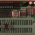
The microbrn software displays, when a model of PIC is selected, where to align pin 1 in the zero insertion force socket, but there's no information on where pin 1 of the socket is (it is at the handle end - see photo 2 below).
I'd bought a pack of SOIC format chips and to use these had soldered one to a DIP format PCB carrier board. When nothing would work, I soldered another one to another carrier, things then started to work. Going back to the original chip I found one pin where the solder had not reached the copper on the carrier - completely invisible from above.
So as often "loose connection" to blame, just that with new software it was hard to tell where the problem was.
I found an LED blinking program [10] for the 12F675 and used the XC8 compiler (free from Microchip) to produce a hex file which easily uploaded with microbrn.
The three surface mount transistors at the bottom edge of the K150 board (just where the text "K150" is) are used to switch positive power and programming voltage. This means it is necessary to select ICSP mode in microbrn when using the external connection socket for ICSP (JST connector at the bottom of the K150). As part of my attempts to discover where to insert the PIC I'd tried to find which pins in the ZIF socket were connected together - something that is more successful with the ground connection.
References
- Windows 10 driver for end-of-life PL-2303 chipsets.
- Picprogrammer
- picpro a kitsrus PIC CLI programmer
- Programming the PIC
- Introduction PIC12F683 Programming Circuits Tutorial
- PIC K150 Programmer
- K150 EBAY PIC PROGRAMMER FOR $7. AND HOW TO GET IT WORKING UNDER WINDOWS 10
- Arduino PIC programmer
- PICPgm A free and simple PIC Development Programmer Software for Windows and Linux
- Simple example program for the PIC12F675 microcontroller
David Pilling's Wiki
Set view

