Checking the accuracy of analogue quartz clocks
started 1st September 2015
See Checking the accuracy of analogue quartz clocks again
The GPS page shows how to set up an Arduino to compare pulse per second signals (PPS) from two sources; typically a GPS receiver and something else. This page is about comparing analogue quartz clocks; I had a lot of clock parts to hand (see Quartz).
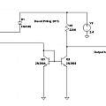
This is the circuit I used. The idea is to measure the clock power supply current, thus not needing a connection to the insides of the clock. The snag may be the voltage supplied to the clock by this circuit varies a little with current. Click to see full size.
The inner tinkerer wants there to be a trimmer capacitor to twiddle and adjust the clock. Or at least to fit a trimmer capacitor. The arguments against this, are cost, a new movement costs about £1. One could replace the crystal, about 10 for £1. It seems that early in the history of quartz clocks, someone came up with the idea of digitally adjusting them; every Nth pulse is skipped. This would make trimming the crystal more difficult. Finally anything added to the clock has to improve the situation and it might not do if it is itself unstable with temperature variations.
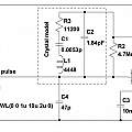
I set out to play with Pierce 32 KHz crystal oscillators in LT Spice. This is not straightforward, tricks are required to make the simulation oscillate, and it is difficult to see if one is investigating the circuit or the simulation. There is an LT Spice discussion group on Yahoo which has a large collection of examples, and that is where I eventually found how to make the circuit oscillate. Some of the values come from a David Johnson circuit [6]. I could not make the trick in [3] using the built in capacitor model work.
Click to see full size.
References
David Pilling's Wiki
Set view


