Started 4th October 2021
See also: Quartz
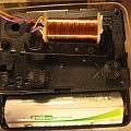
Playing with quartz analogue clock movements it occurred to me that they all have a big coil being fed pulses of current, and it should be possible to detect the resulting magnetic field from outside the clock. This is a lot easier than opening the movement and connecting probes. A previous page has a circuit that monitors the battery current to discover the operation of the clock. Often clocks fail because the electronics stops producing the correct signal.
I was also interested in finding out how accurate clock movements were without setting them going and waiting for days to see if they gained or lost time. It turns out it is possible to instantly measure this.
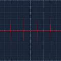
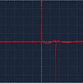
For a detector coil I used a coil taken from an old movement. Connected to an oscilloscope and held parallel to the coil in a clock, waveforms like those below can be seen.
As expected there is one pulse per second, current is turned on for around 30 ms. A voltage is only induced when the current is changing, this explains why there is a spike in one direction and then 30 ms later one in the other. Each pulse has current in the opposite direction to the previous one and this can also be seen - for one pulse the first spike is positive and for the next negative.
Measuring the time between one positive going spike and the next does not result in one second, instead the time between one positive spike and the next but one is two seconds.
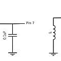
An Arduino program makes sense of this signal. Since the amplitude is around 100 mV no active electronics besides the ATMega 328p are needed. The signal from the coil is fed to one input of the ATMega analogue comparator (digital pin 6), the other comparator input (digital pin 7) is connected to a potentiometer which is used to set a threshold voltage, in practice just above 0V (higher than the noise). When the comparator sees a positive spike the ATMega capture register is used to save the value of timer1.
The program prints out the difference between 1 million and the number of ATMega clock cycles (divided by 16 (for a 16 MHz clock)). Any old Arduino is not going to have a perfect clock frequency, but it allows an easy comparison of analog quartz clocks. For example for one clock I have the displayed number is 328, and for another -56, it is obvious which quartz clock runs faster (the -56 one, because that uses less ATMega cycles per tick).
There are one million seconds in eleven and a half days. A difference of one microsecond per second (one part per million) will become a difference of one second per eleven and a half days. A difference around 400 microseconds as with my clocks is a difference of 24*3600*400/1000000 about 34 seconds per day.
A 1ppm error will be about 16 seconds after six months (often the clocks are moved back or forward every six months). Typical errors in cheap clocks are 10 to 20 ppm, around 180 seconds per six months.
The following video looks at the accuracy of six clocks using the code and hardware described here, comparing results with the pulse per second output of a GPS receiver.


