Quartz
Started November 2014
See also:
Checking the accuracy of analogue quartz clocks
Eurosil 1444 Clocks
When I was a child I wanted to repair clocks. Usually anyone bringing a clock to me took home a bag of clock parts. My talent was taking clocks to pieces, not putting them back together. Fortunately I did not make a career of this childhood interest because disposable quartz analogue clocks appeared. By now billions of them will have been made.
Recently one of my clocks stopped, and it was not easy to get a replacement that fitted in with the surroundings. Given my previous experience I was reluctant to try mending it. However I found a common cause of failure that is easy to resolve.
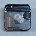
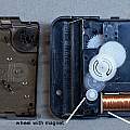
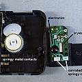
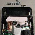
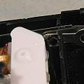
Click to view enlarged photos. Photo 1 shows the back of a typical movement. In photo 2 the clip on back is removed. In photo 3 the top set of gears has been lifted off.
The problem is that the metal used to make the springy battery contacts won't solder, so mechanical contact alone is used for the electrical connection to the little printed circuit. As time goes on these contacts corrode and eventually the clock stops. I opened another non-working clock for the photos and the green corrosion can be seen.
Visible in photo 3 are a black blob which covers the electronics. The metal cylinder, which is a 32768 Hz quartz crystal - 32768 is 2 to the power 15, and can be easily divided down to one pulse per second. That current pulse is applied to the solenoid (copper coil in photo 2). The resulting magnetic field acts on a gear with an attached permanent magnet (see photo 2 again), making it rotate; it's like a tiny stepper motor (WIkipedia Lavet-type stepping motor). The printed circuit in photo 3 is on the back of the solenoid.
The solenoid has a resistance of 259 Ω. Given a battery voltage of 1.5 V the maximum current would be around 5 mA. Supposing the battery has a capacity of 2000 mAH the clock would run for 400 hours at this maximum continuous current. Look at it another way, typically a clock will run for a couple of years (20,000 hours) on one battery, giving an average continuous current of 0.1 mA. To get from 5 mA to 0.1 mA the coil must run at maximum current for just 1/50 th of a second (20 ms) each second. Investigating with an oscilloscope the actual pulse length is around 30 ms (actually 31.2 ms the inverse of 32 Hz (present from dividing down the crystal frequency)).
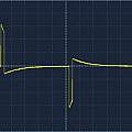
Oscilloscope screen shot at 200 ms by 500 mV, notice the drive signal swings both sides of zero Volts.
I measured the solenoid inductance as 70 mH. When the current through it is turned off, the energy stored in the magnetic field will produce a 'back emf'. The resulting current flowing back into the battery is visible on an oscilloscope connected across a resistor in series with the battery. Presumably this makes rechargeable batteries last a little longer, or a capacitor could be connected across a primary cell to extend its life by a few percent.
Some of these mechanisms have a much faster update time than 1 second; perhaps 8 times a second.
See my Checking the accuracy of analogue quartz clocks page.
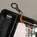
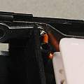
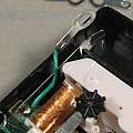
Photos showing one way of fixing the problem with solder tags - wires soldered to the pcb run to the solder tags which fit between the battery and the springy metal.
David Pilling's Wiki
Set view
