Sensor
Started June 6th 2014
This project is a sensor which can measure shallow depths of liquid and report the value by radio. It was used to measure water levels in the crawl space under a house.
I needed to be able to measure depths of water in the range 0 to 15 mm and I wanted a proportional value, not a "water present / water not present" one.
I built a number of versions, the first described on this page uses a capacitive sensor, the second uses ultrasonic ranging, the third uses a laser time of flight sensor, the fourth uses a capacitive proximity sensor.
I have a number of the Oregon Scientific wireless temperature/humidity sensors, these work on 433 MHz, and it seemed a good idea to make my sensor compatible. Presumably Oregon researched what worked well. My sensors use the version 2 protocol and that is what I have kept to.
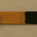
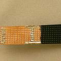
To measure the water depth I built a capacitive sensor I made this from two pieces of Veroboard 25 x 64 mm 0.1" pitch or 9 x 25 holes, soldered together lengthwise. I could have used one piece of the combined size. I made it long because I thought I might have to incline it to get a big enough effect - that did not prove to be the case - operation was OK with the sensor vertical. The bottom section which goes in the liquid is painted to insulate it; two coats of paint were needed. The top section has the electronics soldered on. The tracks are joined into two sets, tracks 1,3,5,7, 9 and tracks 2,4,6,8 these form a capacitor used in an oscillator. The other components are an 82K resistor and a SN74HC14N hex Schmitt trigger inverter. One inverter is used as the oscillator and another to buffer the output of the first. Frequency turned out to be around 250 KHz.
This sensor proved sensitive and stable. The snag seems to be that it rarely dries out completely in the environment I have it in. All that means, is that the frequency for dry in the air is not indicative of no standing water in the crawl space.
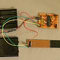
Photographs of the sensor, click to see large version. See the schematics section below for circuit diagram.
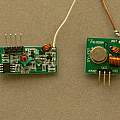
I set off by buying a transmitter and receiver set for £1. At various times I thought these were not good enough and considered bigger aerials, noise suppression and increasing the transmitter power. In fact it always turned out that the things stopping me getting signals were software problems. The basic receiver is a super-regenerative design, identifiable by the coil with a blob of glue. I bought a better super-heterodyne receiver, identifiable by the metal crystal for £3.
The transmitter consists of an oscillator whose power comes via another transistor, the base of that transistor is protected with a resistor. Take the base high and the transmitter transmits, take it low and there is no transmission and no power is consumed.
The signalling scheme is OOK, "on off keying"; the transmitter is turned on and off. Receivers have automatic gain control, receiving at maximum sensitivity until a signal is received. The most interesting thing I did was to connect the receiver output to the audio line input on my PC sound card. This let me hear my sensors (allowing me to think 'if I can hear this so clearly why is the software not displaying a result') and listen to other sensors in the vicinity.
For both transmitter and receiver I ended up using a quarter wavelength whip aerial made from a piece of wire about 17 cm long.
Just because it was easy and I had one to hand I added a DHT11 temperature and humidity sensor.
Photo of the modules, left to right super-heterodyne receiver, super-regenerative receiver, transmitter, DHT11 temperature and humidity sensor; click to see large version.
The core of the project is an ATMega 328 microcontroller. This reads the sensors and transmits the values. To make things easy I bought this ready programmed with the Arduino boot loader. The thing then becomes an Arduino project, the Arduino IDE can be used to generate the software. For programming a FTDI USB to TTL serial interface board is plugged into the sensor, and the IDE is told it is using an UNO R3 board.
There is plenty of information available about how to make a "bare bones Arduino", just enough components to allow the ATMega to work; that is what the main board consists of. The Arduino Pro Mini schematic is a useful guide. I powered it from 4 AA NiMh batteries; voltage is around 5v. It is possible to read the power supply voltage of the ATMega, I do that and transmit it along with the other data. Power consumption would be less with a lower voltage, but that would impact transmitter power.
The ATMega runs in low power mode, every 8 seconds the watch-dog timer wakes it up, and potentially it reads the various sensors and transmits their values. When not doing anything current consumption is around 7 micro amps. The DHT11 and the liquid sensor are powered from ATMega digital outputs (they consume around 1 ma each), allowing them to be turned off, a couple of other ATMega pins read the data values. Pin 5 for the liquid sensor because that pin can be used for frequency counting.
Data is transmitted in the same overall format as an Oregon Scientific temperature/humidity sensor using the version 2 protocol; however I invented a new sensor id, and stored the data in a different format. I also transmitted more data than just temperature and humidity - adding the voltage of the power supply and the frequency of the liquid sensor.
Receiving data is done using an Arduino Uno R3 connected to one of the receivers. This software needs to be able to pick out the data packet from the sensor and then decode it. My version of the code can print out data from standard version 2 Oregon sensors and from my own sensor. Data out from the receiver is connected to pin 3 on the Uno.
The software I assembled is available from the Downloads links below. There are two main Arduino sketchbook projects SensorRX (the receiver) and SensorTX (the transmitter i.e. the ATMega with the sensors attached). I have included the libraries - I modified the frequency counter library so it returned a valid result on the first call. I had two problems with the receiver software. Firstly in the version of the code I set off with the preamble length was 32 bits, later versions of the code set this to 24 bits, and I discovered a reduction from 32 was necessary for my transmitter code. Second it is expected that the sensor will send 160 bits of data, one of my Oregon sensors only seems to send 159 bits, so I changed to this value. The last few bits are a checksum which is not used by the code.
There is a separate archive which contains a debug version of the receiver code; this prints out the duration of each on/off pulse and letters which allow progress through the decoder to be followed.
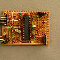
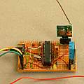
Photos of the complete project; click to see large version. The set of six horizontal pins at the top left of the board is where the FTDI USB TTL serial board is plugged in, when (as shown) this is not in use the 5v battery box is connected to the two power pins. The prototype board has a 0.1" matrix.
Things I would have done differently - bought an Arduino Pro Mini and modified it for low power (see Arduino 32768), instead of messing about building a bare bones Arduino. Experimented with using the liquid as one side of the sensor oscillator capacitor.
Another possibility is to format the data from the liquid sensor so that it is displayed on the Oregon display as a humidity value, allowing observation without having a PC turned on.
What happened
A year on... the main problem is that the crawlspace has high humidity and the water is not clean. The sensor has developed a covering of sand like particles which wick up moisture and do not dry out. As a result there is a considerable time delay before readings are representative.
I have run the sensor from 3 NiMh cells (compared to 4 originally) and it still works. But I've had problems with the batteries over discharging see NiMH.
Eventually I got fed up with the slow response of the capacitive sensor and replaced it with a typical Arduino ultrasonic transmitter/receiver board - continued on HCSR04.
I used a lot of freely available software. Credit to the people who wrote it and made it available.
- LowPower library by Rocket Scream Electronics
- DHT11 Temperature & Humidity Sensor library for Arduino by Rob Tillaart and others
- FreqCounter library by Martin Nawrath
- connectingStuff, Oregon Scientific v2.1 Emitter by Olivier Lebrun
- Decoding the Oregon Scientific V2 protocol by Dominique Pierre
- Oregon Scientific sensors with Raspberry PI by Paul Pinault
- ATMega 328 Secret volt meter by Tinker It
- ATMega 328 Secret thermometer Tinker It
- Oregon Scientific RF Protocol Description
- THE SCHMITT TRIGGER - Talking Electronics
- chirp! - the plant watering alarm
- PCB as a Capacitive Soil Moisture Sensor
- Power saving techniques for microprocessors - Nick Gammon
- Arduino Pro Mini Schematic
- Setting up an Arduino on a breadboard - Physical Computing at ITP
- 433mhz-transmitter-module
- 433MHz Wireless Modules MX-FS-03V & MX-05 (HCMODU0007)
- Archive of Arduino sketchbook SensorRX and SensorTX files and libraries
- Archive of Arduino sketchbook SensorRXDBG debug receiver file
- The only thing here I had not seen elsewhere was using strip board as the sensor, but I have since found: Christmas-tree water-level alert.
Alan
Came across your articles on this whilst looking for info on decoding / using the oregon scientific protocols and was hooked by what you had done. One question occurred to me - would it not have been possible to use a simple float and potentiometer arrangement? Not much fun but simple.... Thanks again really informative!
I have not tried this, good chance you are right. My thoughts are that things only float once they have displaced their weight in water, the float would have to be large surface area and be light to float in a mm or two of water. Other forces to overcome besides gravity, the pot mechanism, surface tension. Grounding on the muck in the water is likely.
David Pilling's Wiki
Set view
