Solder
Started 14th July 2017 - a design for a soldering iron controller
Every line in this is chock full of danger, do not attempt anything described
My grandfather introduced me to soldering, heating the soldering iron in the open flame on the gas cooker in the kitchen, it produced a magical green flame. Moving on to a teenage interest in electronics, I got a Weller iron which lasted me 40 years and still works. It was not creditable that I used the same bit for 40 years. I had a huge tin of flux and when time lagged I would plunge the iron into it for fun.
A more recent revived involvement in electronics saw me give in to "I always wanted one of those" and buy a cheap Chinese made, ebay, Hakko clone, temperature controlled iron (soldering station). The dynamic is different to Weller, one can buy a new iron with bit and carriage from China for £1, but the lifetime of such an iron is often days.
The controller came with an illegal UK plug (no fuse), and inspecting the insides it was worrying to see the earth wire left disconnected. It's cheaper to buy a new iron rather than replacement heaters, even so I've ended up using the Weller to repair it a few times.
What's good about it... well the temperature display gives a clue as to when it is ready to solder, it does reach working temperature faster than the Weller. It's possible to have different irons with different bits.
As a child I positively enjoyed the smell of flux. (Back at primary school, kids would boast how much they liked the smell of car exhaust fumes and breath them in on purpose - that in an age of leaded petrol.) By now flux is a very bad thing, I got a server fan (much more powerful than the average PC case fan) and turned it into a fume extractor. I'm still using 60:40 leaded solder, another very bad thing.
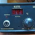
The soldering station is styled 937D - out on ebay the difference to note is between soldering irons (handles) with pins (male) or sockets/holes (female) i.e. on the cable attached to the iron. The female ones have the A1322 element which features a thermocouple for monitoring temperature. The male version has the A1321 element with a thermistor. I am in A1322 land.
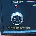
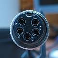
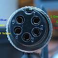
First two photos - pins. Last two photos connector on the end of iron cable - holes. The final photo shows the pin connections. The heating element has a resistance around 10 Ω and the thermocouple sensor is about 1 Ω.
There is an eevblog forum discussion: Hakko 936 ceramic heater A1321 vs fake comparison which covers the differences in the two elements, connections etc. From this there is also an A1323 element made of stainless steel, my soldering station came with these, I've never been able to find them at a reasonable price and since they lasted such a short time it's probably not a bad thing.
One way of damaging the element is to try changing the tip whilst the iron is hot.
What I wanted was a way of using one of my irons for melting plastic at temperatures lower than the minimum the controller supports (200 °C). I only intend doing this very rarely. I have a bench power supply that could supply power (DC). Many of the controllers use triacs and are intended for AC.
Searching for "A1322 soldering iron controller" did not produce anything usable, but I eventually found two good designs The Digital Controller for Amazing T12 Soldering Tips and Soldering Iron Controller for Hakko 907. These are for two Hakko variants, the first has a thermocouple in series with the element and the second has a thermistor. A simpler version of the first one would work with A1322 based irons.
Ebay does contain lots of soldering iron control boards, for Hakko/clone variants, but they have the look of closed firmware which makes going with a DIY design attractive.
Soldering station design
My thought was to do something simple. An Arduino Leonardo which has differential ADC along with a built in amplifier, means no analogue electronics. A logic level MOSFET can be driven directly from the Arduino. The user interface consists of a Nokia 5110 LCD display and a rotary encoder. All that spoils this simplicity is needing a buck converter to protect the Arduino from the potential power supply voltage of 24 V.
The soldering iron thermocouple connects directly to the Arduino analogue pins A4 and A5. The IRLB3034PbF MOSFET is driven by digital pin 6 and switches the input power supply to the iron heating element. There is a 100 Ω resistor between the gate of the MOSFET and the Arduino and a 100 KΩ resistor between gate and earth.
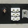
Positive power in goes to the iron element and the buck converter. The other side of the element goes to the MOSFET drain. Earth joins the buck converter and the MOSFET source. These connections take place in the "choc block" (terminal strip) connector on the back panel - which was a few sizes too big for the wires.
Connecting the Nokia 5110 display
//      SCK  (SCLK) - Pin 8  via 10K Ω resistor
//      MOSI  (DIN) - Pin 9  via 10K Ω resistor
//      DC (D/C)  - Pin 10  via 10K Ω resistor
//      RST  - Pin 11  via 10K Ω resistor
//      CS (CE)   - Pin 12 via 1K Ω resistor
//      VCC - 3.3V
//      Light - Pin 5
//      GND - GND
This LCD is driven using the library [3].
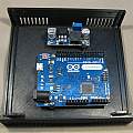
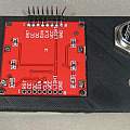
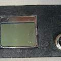
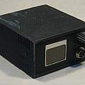
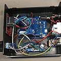
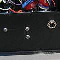
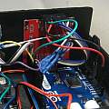
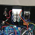
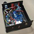
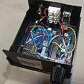
First photo shows the Leonardo and buck converter in the box. Second photo shows the back of the front panel with the LCD mounted using small self tapping screws (1.4 mm diameter x 3 mm length); this version of the LCD has current limiting resistors for the LED illumination built in (as described in [1]), which means it is only necessary to short the light pin to earth to turn the LEDs on. Third photo shows front of the front panel. Final photo inside the back panel.
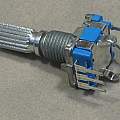
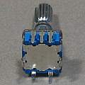
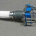
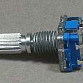
The rotary encoder is an EC11, there are five pins on the back, three for the rotation part (earth, phase 1 and phase 2) and two for the push button (earth and signal). It seemed nice to connect all five wires to the digital pins on the Arduino (2-6) using a five pin Dupont connector - that means using a couple of digital pins to supply zero volts, but they are not needed for anything else. That went wrong when I needed an extra pin (to control the LCD light) and when I found pin 7 on the Leonardo is available to handle interrupts (like pins 2 and 3 on the Uno). Pins 2,3 and 4 connect to the rotation part of the encoder - pin 4 supplies zero volts to the middle of the three pins on the EC11 and also to one side of the push switch. Pin 7 meanwhile is connected to the other side of the push switch.
Software for handling the rotary part of the encoder comes from [11]. Software for handling the push button part I wrote myself (!).
The case is 3D printed and a customised version of [9] - bits worth copying are the feet layout for an Arduino and the pads for mounting the LCD. The control knob is also 3D printed and a customised version of [10]. Open SCAD files for both can be downloaded below.
- OpenSCAD files for case and knob (30th August 2017)
- Arduino project Solder04 - source code (1st September 2017)
Criticism
I'm never going to use this without being there all the time it is powered; it will run from a bench power supply which lets me see exactly what is going on and provides current limiting. But for a "commercial product" things would be different; the microcontroller should make use of a watch dog timer to reboot in case of crashes, the temperature of the MOSFET should be monitored and there ought to be current limiting in case of short circuit. An idea stolen from 3D printers - there could be a check for thermal runaway - is applied power resulting in the bit getting hotter.
The MOSFET is expected to run at room temperature, so the heat-sink is for decoration, if it did start to get hot the PLA 3D printed case would bend.
It would have been better to use a PID algorithm to control turning on the power.
I used the parameterised equations from [8] to convert between voltage and temperature (and back). For the regime of interest these give good enough results (within a handful of degrees). But that is a matter of luck with mistakes cancelling one another out. I've not allowed for the "cold" junction temperature and the temperature of the sensor is not the temperature of the bit - something which is apparent as the iron warms up and cools down.
A better idea might be to simply calibrate the iron (measure the sensor voltage at a number of known bit temperatures) and interpolate between the calibration points.
- NOKIA 5110 ARDUINO
- Graphic LCD Hookup Guide
- Library: LCD5110_Graph
- Fast PWM on Arduino Leonardo
- IRLB3034PbF datasheet
- Modern Thermocouples and a High-Resolution Delta-Sigma ADC Enable High-Precision Temperature Measurement
- Using polynomial equation to determine thermocouple temperature
- NIST ITS-90 Thermocouple Database
- The Ultimate box maker
- Customizable Knob!
- Encoder library - Paul Stoffregen
- David Pilling's differential ADC library
David Pilling's Wiki
Set view
