Strobe Timer
Started October 2013
This is a project for the Raspberry Pi running RISC OS which analyses the output of strobe or flash lights on cameras.
The hardware side of the project consists of a photo-diode board connected to the Pi. There are only three connections, ground, positive power (which is connected to the 3.3v line on the Pi GPIO bus), and the digital output of the photo-diode board (which is connected to one of the Pi GPIO pins via a 1K resistor).
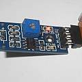
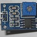
The photo-diode board consists of a photo-diode connected to a comparator. I bought mine off ebay from China for around £1.50. When the diode senses light the board gives a zero output, when the diode senses dark it gives a one output. There is a small potentiometer on the board which allows the point between light and dark to be adjusted.
There are two things that are of interest in the output of a strobe light. First the duration of the light pulse - typically this is used to adjust the exposure. An object further away needs more illumination and to do this, the duration is increased - rather than increasing the brightness of the light.
Secondly the visible flash consists of a number of pulses. Usually there will be a short pulse of light to work out how bright the second longer main flash should be. There may be other pulses to suppress 'red eye' or control slave flashes.
Duration of the light pulse is interesting because shorter pulses mean less motion can occur.
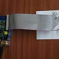
I connected the Pi GPIO to the photo-diode board via a length of ribbon cable, a bit of stripboard and an IC socket. I put a 1K resistor between the photo-diode output and the Pi GPIO pin, to protect against the situation of the Pi pin being set up as an output.
I found that from BBC Basic using the GPIO module SWI I could read a GPIO pin about 20,000 times a second. The code dimensions some memory (20,000 bytes or one seconds worth), and reads the photo diode output into it. From reading the system time at the start of this loop and at the end, I can work out how much time a single reading takes. Times are shown in milliseconds - ms - thousandths of a second. Given 20,000 readings resolution is 0.05 ms.
When the program is run it waits for the photo-diode to be illuminated, it then drops into the loop reading data. After that is complete it analyses what has happened.
Below is sample output from various cameras and flashes. The BBC Basic source can be downloaded click here. It uses Tank's GPIO module which must be installed and is available from here.
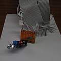
Photos show the setup - click to view full size.
A reaction to this page came from David Daniels, he pointed out that replacing SYS"SWI_NAME" with SYS SWI_NUMBER will give an increase in speed. I tried this, and from reading 20,000 values per second the code became able to read 300,000 values per second. However the results changed - much speculation why, eventually the results from both lots of code became similar.
I found a page here where strobe times are measured using an oscilloscope and many are much shorter than those presented here. Strobes continue to give out some light for a long time, not enough light to have an effect on photographs but enough to trigger the photo-diode.
This raises the point that the point between light and dark needs picking well. For example it is possible to adjust the photo-diode board so that it indicates light all the time - that does not imply any flash measured has an infinite duration.
Sony Alpha 200 DSLR built in flash
Time 0 ms duration 0.693ms
Time 4.95 ms duration 0.792ms
Time 9.504 ms duration 0.792ms
Time 14.454 ms duration 0.5445ms
Time 107.118 ms duration 5.742ms
Polaroid PL108af compatible flash on Sony Alpha 200
Time 0 ms duration 1.98ms
Time 106.5735 ms duration 2.1285ms
Polaroid PL108af compatible flash on Sony Alpha 200 closer to object
Time 0 ms duration 1.782ms
Time 111.276 ms duration 0.7425ms
Canon IXUS 75
Time 0 ms duration 0.85ms
Time 58.25 ms duration 0.8ms
Canon Powershot a810
Time 0 ms duration 0.85ms
Time 76.15 ms duration 0.75ms
Meike 410 manual strobe on default setting
Time 0 ms duration 1.9305ms
Meike 410 manual strobe set to minimum
Time 0 ms duration 0.99ms
Canon Powershot a95
Time 0 ms duration 0.693ms
Time 118.503 ms duration 0.792ms
December 2016
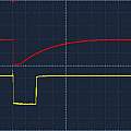
Eventually I fed the analogue (red) and digital (yellow) outputs from the photo-diode board into my oscilloscope. The trace below is for the Meike 410 on minimum power, 2 V and 500 μs per division.
The results confirm the time from the Pi but since the photo-diode saturates one can't say the time is for 50% brightness.
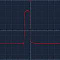
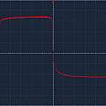
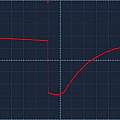
I bought some PD204-6C photo-diodes and using them with a single load resistor observed much shorter strobe times with no gradual decay. First photo Meike 410 on minimum power, 1 V and 100 μs per division, PD204-6C. Second photo Meike 410 on minimum power + 7, 1 V and 100 μs per division, PD204-6C. Third photo Meike 410 on minimum power + 7, 1 V and 500 μs per division, photo-diode board.
The Meike has a system of 8 big steps each of which has 7 small steps - total 56 brightness levels.
The schematic of the photo-diode board is here:
Light Sensor Module - Photodiode
The photo-diode has a 10K load resistor with a 100 nF capacitor to ground - the analogue output comes direct from the junction of the resistor and diode. It seems the exponential decay comes from the capacitor and not the light. The time constant of 10 K and 100 nF is 1 ms which matches up with the results.
David Pilling's Wiki
Set view
