Temp Sensor
Having created a wireless liquid level sensor and a logger for wireless sensors, all compatible with the Oregon sensors, it was inevitable that one of my Oregon sensors stopped working. Using the wireless liquid level sensor design I could make another sensor, the interest is how simple it could be. It would be cheaper than buying a new old Oregon; the sensor described here costs around £3; an Oregon sensor would be many times that. A few thousand quids worth of software engineering are involved, but all that is available for free from the download link below. Eventually I fixed my Oregon sensor by taking the thermistor from another broken Oregon sensor, but I'd started this project by then. (See Replacing the thermistor in a Oregon TH122N sensor for how to fit third party thermistors).
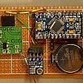
The core for the sensor is an Arduino Pro Mini; thinking of making the sensor compatible with Oregon receivers I required an accurate low power clock and converted the Pro Mini to use a 32768 Hz clock crystal, as described in Arduino 32768. Oregon sensors transmit data every 40 seconds exactly.
Originally I was going to use the temperature sensor which is built into the Atmega 328 processor in the Pro Mini. I found that to be of poor resolution. I had to hand a BMP 180 sensor. This measures temperature and barometric pressure. It is very sensitive, holding ones hand near it causes the temperature reading to change. Current consumption is low around 6 μA in standby mode. I chose to power off the sensor when the processor is in sleep mode.
Power to the BMP 180 comes from an Arduino output pin. To turn off the power it is not good enough to set the pin to zero. Doing that results in the BMP 180 hanging. Instead the pin is set to be an input. Given the low power use of the BMP 180 and the time to restart it, it is a close decision whether to power it off or not.
By using the code described in Arduino 32768 I reduced current consumption when sleeping to 1 μA. Effectively this does not drain the battery. The problem is the power used when the processor powers up. A transmit sequence consists of 140 ms reading the BMP 180 sensor (it takes 100 ms to stabilise after being turned on); followed by two 200 ms periods with the transmitter on. During the BMP 180 sensor read period current consumption was 3.7 mA and during transmit 7.4 mA; an average of 6.3 mA for half a second. When measuring current I had a substantial capacitor connected across the power lines so values are realistic averages.
Instead of waiting 100 ms for the BMP 180, a better idea would be to transmit the previous value read and read the sensor after the transmit sequence - running the data transmission and sensor power up in parallel.
I'd bought some CR2032 batteries at Poundland (8 for £1) and thought they looked like they'd be OK. Picking batteries on grounds of aesthetics combined with economics ended up making me work hard on reducing power use.
Capacity of a CR2032 is supposed to be 200 mAH; giving a run time of 132 days. This is not good enough. Most of the 3.7 mA used during the BMP 180 read is due to the processor. By turning off the ADC and SPI interfaces, and setting all pins to outputs (at zero). I shaved this down to 2.7 mA. However a bigger saving comes from reducing the clock speed from 8 MHz to 1 MHz; this reduces the processor power consumption to well below 1 mA.
The Oregon protocol transmits the data twice. Another big saving can be made by only transmitting data once; effectively this halves power use. I found that one of the data transmissions was not being received anyway. I eventually increased the preamble burst to 48 bits to fix this and only transmitted the data once.
Running at a low clock speed has problems. The Oregon transmit code depends on delayMicroseconds() which won't be accurate. In addition the code for wiggling the transmitter output which uses digitalWrite() is too slow. I replaced the delay with __builtin_avr_delay_cycles() and used digitalWriteFast2(). All that is then needed is to set up the wire and twi libraries to use the slower clock speed.
At the end of this a CR2032 battery is predicted to last a year. An average current of 25 μA giving 8000 hours from 200 mAH. Average power use is 75 μW. There are 8760 hours in a 365 day year.
So how long did the battery last? After a couple of weeks I found the sensor with the pin 13 LED flashing on and off rapidly. Seemingly it would start up, then the voltage would fall and it would do a reset and start again. Probably it had got into this state after a transmit operation had pulled the voltage too low. Interestingly it had been flashing the LED for some hours, proving there was plenty of power in the battery but not at a high enough voltage.
Connecting a big capacitor across the power lines allowed normal operation but only for a few more hours. Research reveals that the standard 200 mAH capacity (and the flat voltage discharge curve) is only at low currents (less than 1 mA).
At which point "brown out detect" came to mind. The default brown out detect voltage programmed into my Pro Mini was around 2.7 V as was the battery voltage when under load. I reprogrammed the efuse; the default was 0x5; I changed the value to 0x6 which sets a typical brown out voltage of 1.8 V. I suspect some power saving could be achieved by setting the efuse to turn off brown out detect all together.
This web page shows how to
connect the USBASPI programmer to the Pro Mini. The Avrdude command line I used was:
avrdude -p m328p -c usbasp -P USB -U efuse:w:0x6:m
After changing the fuse byte the sensor started to work again.
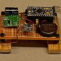
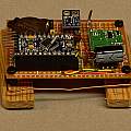
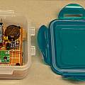
Photographs of sensor, click to enlarge
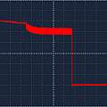
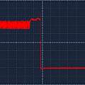
The sensor continued to work for a couple of months. Then out of interest I looked at the power to transmitter output with an oscilloscope, this goes high for the whole duration of the time the controller is not sleeping. I'd failed to correct several delays for the lower clock speed and the sensor was powering up for a lot longer than it should have done. Having fixed that the situation was as shown in the first image below. It is apparent that the transmission of data (the right hand half) takes around 200 ms but nearly as much time is used reading the BMP 180. I exchanged the transmit / read BMP 180 order, giving the result in the second image - a reduction of 100 ms or 25%. Another change between the two images is the removal of the large capacitor across the power supply, the exponential decay in voltage whilst data transmission is going on is no longer present. Given the receiver adapts to the received signal, level changes may be bad. Implicit in these traces is the current consumption. The newer version of the source code is below.
Scope views, click to enlarge
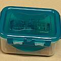
Another observation, the BMP 180 is a pressure sensor, the whole project lives in a lock tight food container, which seemed like it might be air tight. However it was noted that immediately after sealing the container the pressure measured went up and then over a few minutes returned to the previous value. Air tight does not necessarily mean the pressure won't vary with the outside pressure - the box can flex a little. However exchange of air with the outside opens the possibility of moisture entering.
I used a lot of freely available software. Credit to the people who wrote it and made it available.
- Decoding the Oregon Scientific V2 protocol by Dominique Pierre
- Oregon Scientific sensors with Raspberry PI by Paul Pinault
- connectingStuff, Oregon Scientific v2.1 Emitter by Olivier Lebrun
- Bosch Pressure Sensor BMP085 / BMP180 readout routine for the Arduino platform by Leo Nutz
- digitalWriteFast library by John Raine
- Archive of ArduinoTemp12X sketchbook and libraries - in other words all the sources for the Arduino part of this project (24th April 2015).
- Old version ArduinoTemp12 - (10th February 2015).
David Pilling's Wiki
Set view
