3D Printing
Covers mid 2016 to mid 2017, later 3D stuff is on separate wiki pages see the index
I bought a 3D printer, £135 on ebay (shipped inside the UK). It is a common product, claims to be CTC (but may be a clone) has an electronics board which is a Geeetech 2560 clone. Made of 5 mm plywood. It is good value for money, even coming with a big (1 Kg) reel of filament and a screwdriver. There is a YouTube video of what is almost identical [1]. Typical listing on ebay "2016 Upgraded Full Quality High Precision Reprap Prusa i3 DIY 3d Printer LCD".
I got a lot of parts and few instructions, the most useful thing was the photo in the ebay listing. However it was fun working out how it went together and didn't take long. Initially it would not extrude, I found the motor driver carrier for the extruder motor had a bad solder joint. After fixing that it still would not extrude properly. I replaced the A4988 stepper motor controller carrier with one based on the TI DRV8825 and it all worked.
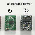
Picture of motor drivers, two A4988 and two DRV8825, these are oriented the same way around (as regards pin function e.g. power supply pins), notice the small variable resistors ('pots') are on opposite ends. The picture shows the correct way to twiddle the variable resistor to increase current - the last, purple, one works the opposite way to the others.
It is necessary to remove two jumpers on the electronics board when using the DRV8825 because it can do 32 microsteps per step and the jumper setting for 16 microsteps is different.
Upgrading the extruder
Eventually the hotend nozzle blocked and I took the opportunity to replace the plastic extruder with "3D Printer Extruder Aluminum Frame Block DIY Normal Hand Kit fr Reprap i3 MK8" which looks better, and probably is, but didn't make a lot of difference. The problem buying them is that they come in left, right (normal) and centre varieties.
A new hotend heater block with 5 mm throat was needed. There's scope to fit the throat the wrong way around. I eventually ended up with the loose PTFE tubing at the heater end. A thin M5 nut is needed. Half height will do, but I came across a much thinner one, maybe from a volume control.
All this fits without any metal work.
I also changed to a 0.2 mm nozzle, results were better, but slower. I soon moved back to 0.4 mm (via 0.3 mm) as the best compromise of speed and quality.
I then had a series of failed prints. One variety consisted of the filament pilling up in the extruder mechanism. This was due to my fitting the extruder fan heatsink the wrong way around (filament gets hot and instead of being pushed through the hotend it bends and spills out).
I also had episodes of the heater cartridge coming out of the hotend and molten plastic running out of the threads around the throat. What I learnt is that the various nuts and grub screws should be tightened whilst the hotend is hot.
More hot ends followed, another ebay one was a lot better designed than the first, and then I moved to E3d v6 clones. My designs for fitting these are here E3D v6 Mount and E3D v6 Bowden.
[3] is a useful reference on the MK8 extruder.
X axis idler tensioner
I was impressed the printer kit came with files to print replacement parts. When the X axis idler tensioner broke, I discovered that these files did not include all the parts and were only gcode anyway. I ended up designing a replacement which can be found on Thingiverse [5] see also my version of a GT2 belt clip [6] (replacing the tensioner requires re-tensioning the X axis belt).
Fitting failure
Once I started to print components that fit together I had problems - they would not fit. Holes would be too small, and pegs too big. This I discovered was due to the default number of E-steps (extruder steps) being wrong. It is 105 per mm and I got good results with a value of 85. The supplied firmware won't allow new values to be saved in its non-volatile memory.
Upgrading the firmware
It'd be nice to upgrade the (Marlin [8]) firmware to sort out the E-steps problem and get new developments. I found a discussion [2]. From comments it seems that often it is necessary to write a boot loader to the processor before the Arduino IDE can be used to do the upgrade.
I set off using an ICSP programmer, the idea being to read the old firmware just in case I could not get the new version to work and to install a boot loader. The SD card socket should contain the necessary connections. I used an USBasp programmer and arvdude. [7] explains the pinout of the SD socket and notes that one cannot rely on the polarising lug on the socket - mine is the opposite way around to the photo in the reference.
Anyway I failed miserably to get avrdude to communicate with the processor. I gave up and simply used the Arduino IDE and programmed new firmware via the usual USB connection. In other words the Arduino boot loader was already present in the processor.
A combination of following the diff of the default Marlin configuration file with the Geeetech version, and having printed out the settings for the original firmware got me a new version of Marlin which appears to do everything the original firmware did.
Safety
Do not take my advice and what you do is at your own risk. There are jokey references to 3D printers catching fire, and at first I thought this was the typical comment on any electronic or electrical equipment. Eventually I read about the mechanisms for disaster.
The printer has a heated bed and an extruder heater (hotend), both are controlled by the printer's micro-controller via MOSFETs - thermistors provide temperature measurement. One possibility is a software crash when the heaters are on. Another is the MOSFETs going short-circuit.
A more interesting event is the thermistors becoming mechanically disconnected from the heaters - it is easy enough for the heater cartridge to come out of the hotend. The Marlin firmware has code to spot this sort of "thermal runaway", however enabling it is optional and a test of the original firmware led me to believe it was not enabled.
The result of any of these is a heater being powered on continuously and getting hotter until heat generation is balanced by radiation. That may be harmless or it may ignite the plastic in the printer. On my printer there is a piece of wood under the heated bed. The auto ignition temperature of wood is 180 °C and for PLA is of the order of 340 °C.
When I was a child I pulled an old electric blanket to pieces and was intrigued to find a bi-metal thermal cutout inside it. Old fashioned (CRT) colour televisions (which once had a reputation for bursting into flames) were by their later days full of special versions of components (like resistors) which would cause them to fail safely. Here there is no such physically based independent cut off.
Whilst fitting a thermal fuse to the heated bed I also replaced its thermistor which from the start had been showing 30 °C at room temperature (around 16 °C).
In reality the heated bed when continuously powered will not get above 80 °C due to heat losses, but the power supply and connections are likely to overheat when supplying high current for a long time.
Mains power insulation was not good, nowhere near the standard of approved equipment, but I thought it was good enough for someone experienced with electricity. Eventually I found an exposed piece of metal carrying the live side of the mains.
Z axis couplers
As supplied the two Z axis 8 mm threaded rods had a 5 mm section at the end and PVC tubing was supplied to link this to the 5 mm stepper motor shafts. This looks bad but actually worked well. After a while I replaced it with two 5 mm aluminium flexible couplers. I butted the rods and the shafts in the couplers forming a rigid coupling - there was less wobble in the threaded rods.
Eventually I replaced the threaded rods with lead screws, these are 8 mm diameter, 2 mm pitch, 8 mm lead, 4 threads, one revolution drives the nut 8 mm forward.
Levelling the bed
I originally levelled the bed by eye (viewing the distance between the nozzle and bed) and this seemed to be pretty good. Much more critical is getting the zero point of the Z axis correct. Too low and prints have a squished out bottom. Too high and they don't stick. I also got a set of feeler gauges and a dial gauge (indicator). The dial gauge is good because it gives a numerical value, a sense of how far out of level a place is. To attach it to the extruder I printed a slim version of the motor bracket in [9] and printed a new back for the dial gauge with a mounting point for the motor bracket. Thingiverse has lots of dial gauge mounts and replacement backs [10].
The other thing one can do with a dial gauge is measure the accuracy of movements in the X, Y and Z directions. See 3D Printer Motion Accuracy.
My initial experience of levelling the bed turned out to be "beginners luck", eventually it became a nightmare of hours spent twiddling. An automatic system is essential, I devised my own based on a strain gauge, which is described here - Z axis probing and auto bed levelling. This is a huge improvement and gives fantastic results.
Motion resolution
From the outset the X and Y resolutions of 78.74 steps per mm impressed me by being magically precise numbers. Later I discovered the theoretical value was 80 and 78.74 crops up as the right value for different hardware. The stepper motors are 1.8 degree ones, 200 steps per full circle. I replaced the X and Y axis ones with 0.9 degree steppers (400 steps per full circle) along with 16 tooth pulleys, the result is to change the resolution to 200 steps per mm.
Stability
There's not much point worrying about resolutions less than 1 mm when parts of the machine can move many mm on their own. I went around the printer and found various areas where slight pressure would make things move. To fix this I followed the Hephestos Y axis modification in [11] and printed the Z axis brackets in [12]. I also obtained a chunk of old kitchen worktop and put the printer on it. After all this results improved - measured by how smooth printed pieces are.
Upgrades
Hotend, E3D v6 hotend (see E3D v6 Mount and E3D v6 Bowden)
Extruder
Firmware
X axis tensioner
0.9 degree stepper motors and pulleys for X, Y and extruder
Heated bed thermal fuse and thermistor
Extruder motor driver
Flexible shaft couplers
Trapezoidal lead screws for Z axis
Duct/cooling fan
Hephestos style Y axis
Z axis brackets
Kitchen worktop base
Z axis probing and auto bed levelling
Conclusions
It seems there is always something wrong with these cheap 3D printers. A result of low costs and lots of things to go wrong. For me the something was the motor driver carrier - having fixed that, the printer worked well.
But not well enough, I wish I'd not imagined I could improve the printer. It is not true that every upgrade improves results; which upgrades are worth the effort is something one learns. Whoever put the printer package together had done a good job of picking components.
If I was starting again I would keep printing a test piece to see if results were improving.
Some upgrades were essential like fixing the broken pulley, others like upgrading the firmware were simple and gave a good return.
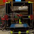
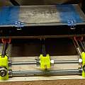
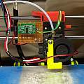
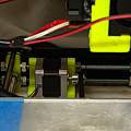
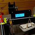
Photos show how the printer ended up looking.
Marlin compilation woes
As a backup I bought "Reprap RAMPS1.4 12864 LCD display controller + smart adapter Mendel,Prusa 3D Printer" along with a RAMPS1.4 board and Arduino Mega 2560. I set off to compile Marlin, and got the error message:
In file included from /tmp/arduino_build_286188/sketch/ultralcd.cpp:39:0:
dogm_lcd_implementation.h:85: error: 'DOGLCD_CS' was not declared in this scope
 U8GLIB_DOGM128 u8g(DOGLCD_CS, DOGLCD_A0); // HW-SPI Com: CS, A0
dogm_lcd_implementation.h:85: error: 'DOGLCD_A0' was not declared in this scope
 U8GLIB_DOGM128 u8g(DOGLCD_CS, DOGLCD_A0); // HW-SPI Com: CS, A0
I'd uncommented:
#define REPRAP_DISCOUNT_SMART_CONTROLLER
Wrong! I should have uncommented:
#define REPRAP_DISCOUNT_FULL_GRAPHIC_SMART_CONTROLLER
I'd also uncommented:
#define DOGLCD // Full graphics display
which I should have left alone.
References
- $154 CTC 3D Printer Kit from eBay, Unboxing, Assembly and Test
Building a 3D Printer Kit - CTC/Geeetech Ebay Prusa i3 gt2560 Bootloader
- Geeetech MK8 Extruder Tips & Tricks :: 3D Printers
- GT2560
- Tensioner Idler (CTC, Geetech, Pro B)
- GT2 Belt Lock clamp
- Reflash Bootloader on GT2560
- Marlin on Github
- Motor Mount Extruder
- Dial Indicator Backplate
Dial Indicator Back
Dial Indicator Back Plate - eBay Prusa i3 Y axis mod
- Prusa i3 Pro B Z axis top brackets with blocks for strengthening rods
David Pilling's Wiki
Set view
