VC 99
Started March 2015
There are lots of pages describing how to extract a serial data stream from the Vichy VC99 multimeter. There's an unused pin to which one can connect a wire, then hold down the Rel button and bursts of 2400 bits per second data appear. Various techniques have been used to handle the data whilst providing electrical isolation.
A new possibility is the ESP8266 WiFi board. It comes with a serial port and WiFi connectivity. It does work when connected to the VC99. In particular it will work on the power supply voltage available from the meter; which running from 2 AAA cells is expected to be in the range 2.4 to 3 V. The serial data line from the VC99 is normally high and only goes low when serial data is present. There is no "serial interface enabled" pin; the only indication that the extra hardware should be active is the presence of serial data. A handful of bytes is sent every 0.6 seconds - meaning most of the time there is no serial data.
ESP8266 bridge software is available which takes serial data and sends it unmodified to the network; which is all that is needed.
There are various ways to connect the ESP8266.
- Connect to the meter switched power supply, permanently enabled - drain is 70 mA.
- Connect to the meter switched power supply, toggle the ESP8266 CH_PD enable pin when serial data is available.
- Connect to the meter battery, power up the ESP8266 when serial data is available.
Connecting to the meter switched power supply requires an extra connection to the meter PCB, slightly more complicated, but means that when the meter is off the power to whatever extra hardware is connected is also off; there's no problem with power leaking through the serial data connection.
Option 1 needs no more than wires. A variation might be to use the light sleep mode and wake when a GPIO pin goes low (when serial data appears). Standby current is claimed as under 1 mA. Expectation would be that the ESP8266 would have some "wake on serial data" functionality but seemingly not.
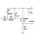
Options 2 and 3 require progressively more complex circuits. This circuit can be used for option 2. Click to view full size.
Instead of using the BSS84 bog-standard p-channel equivalent of the 2N7000 FET, an AO3401 allows this circuit to not just toggle the chip enable line but instead to supply power to the ESP8266 implementing option 3. However operation depends on the leakage through the Schottky diodes and the FET being just right to give a useful time constant. With 1N4148 diodes the circuit takes many seconds to power off, with an AO3415 it powers off between bursts of serial data.
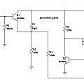
The next circuit is less critical and works for option 3. Click to view full size. 1N4148 diodes can be used.
I built this circuit on a single sided surface mount pcb the same size as the original ESP8266 board (aka ESP-01) about 14 x 25 mm. I replaced the square pins on the EPS8266 with round machined pin header sockets. The add-on pcb also has round pin header sockets inserted from the non-copper side but with the holes in the pcb oversized (1.5 mm) so that enough of the pin on the bottom of the socket protrudes to mate with the socket on the EPS8266. The result is a double decker board object with all the components facing inwards.
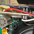
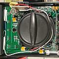
There's room to fit this double board on edge inside the VC99 by the side of the transistor tester socket. Three wires connect it to the VC99 pcb - 3 V power (plus/minus) and serial data.
Below is the Eagle pcb design software project folder for the version 3 pcb. Note I have not tested this version it has a small fix to the version 2. Also contained are pdf versions of the schematic and board. The board is so small the free version of Eagle can be used. By the time I made the pcb I'd increased the 220K resistor to 2M and actually made the board with all 2M resistors replaced with 2M2. The diodes are BAS85, the smd version of the BAT85, I could not find these in the Eagle libraries and picked some obscure part with the same package.
VC99 links
Hacking multimeters for data logging
Cheap DMM multimeter hack
Multimeters and their chips, with computer communication
FS9922 DMM chip datasheet
Adding a wireless link to the VC99 - Nathan Chantrell
ESP8266 links
ESP8266 NodeMcu and Lua language and some Arduino issues
ESP8266 Quick Start - Peter Jennings
Transparent bridge software
Reducing ESP8266 power consumption using deep sleep - Malcolm Yeoman
David Pilling's Wiki
Set view


