Waking from sleep mode
I've used the low power sleep feature of the ATMega in various projects. In doing so I've covered the many possibilities for waking the chip up.
The only reason to use sleep mode is to save power, as a result other tricks for reducing current usage come into play. There's little point putting the processor into sleep mode whilst having an LED power indicator turned on.
For wireless sensors there can be an advantage in accurate sleep times - if you know when the transmission is coming you can save power at the receiver or even detect the signal better.
Watch dog timer
In favour, simple. Against, not very accurate. Typical current 7μA. Maximum sleep time 8 seconds. Example project Wireless liquid level sensor.
32768 Hz watch crystal
In favour, low cost; a watch crystal can be had for 10 pence; accurate to one or two seconds a day. Typical current 1.4 μA. Maximum sleep time 8 seconds. Example project Arduino using 32768 Hz crystal.
For periods longer than 8 seconds the processor has to wake a number of times and go back to sleep. How much does this cost? I observed the processor being awake for 4 ms whilst the current was 6 mA each time. Averaged out this comes to 3 μA.
The 4 ms appears to be built in to the ATMega 328 to allow the internal oscillator to stabilise. See the datasheet 9.2.2 Clock Startup Sequence and 10.6 Power-save Mode "The wake-up period is defined by the same CKSEL Fuses that define the Reset Time-out period, as described in ”ClockSources” on page 28"
External interrupt
In favour, lowest power usage, all processor clocks can be turned off. For a pound one can have an external temperature compensated clock accurate to one or two seconds a month. Typical current 0.2 μA. Maximum sleep time - unlimited. Example project Wireless sensor data logger.
Bera Somnath suggested to me that a simple RC circuit could be used to provide the external trigger to wake up the ATMega. The resistor is connected to the positive rail, the capacitor to ground and the common connection goes to an ATMega pin. The ATMega is set up to use the pin (as an output) to discharge the capacitor, then sets the pin to be an input with a rising edge interrupt enabled on it, finally the processor enters sleep mode.
This does work. But there is a problem, as the voltage on the input pin rises the current consumption of the ATMega goes up, long before the rising voltage wakes the processor, the current will be nearly 1 mA. This is hinted at in the datasheet section 10.10.6 Port Pins "If the input buffer is enabled and the input signal is left floating or have an analog signal level close to Vcc/2, the input buffer will use excessive power."
Using a SN74HC14N hex Schmitt trigger inverter between the RC and the ATMega showed the same effect. Confirmed in this TI Application Report [1].
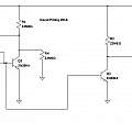
I devised a circuit to trigger the ATMega which does not have this problem; the combined current usage is under 0.5μA. Time between wake up events is over two hours; this time can be easily adjusted by changing the resistor and capacitor values, but it is unlikely to repeat accurately; the circuit is based on the designs on the PUT page. Click to see large image.
This circuit does oscillate (it is astable). But one could have a simpler version (a monostable) that interrupted the ATMega and then use the ATMega to set the initial conditions for another period (like the RC circuit).
All one is doing is preserving the memory contents of the ATMega because one has little idea of the time of the wake up.
David Pilling's Wiki
Set view
