Z Probing
Started 4th June 2017
I (eventually) describe using a strain gauge as a Z axis probe
See also Opto position sensor
See also CR-Touch sensor
Whilst homing the X and Y axes is not of much interest, homing the Z axis is critical, because it controls the height of the extruder nozzle when printing the first layer. Too high and the print won't stick. Too low and it will have an overlarge bottom ("elephant foot").
The simple approach as used on the Prusa I3 is a micro switch on the printer frame which is triggered by Z direction movement of the X axis. The nozzle is also attached to the X axis, but there is a lot of machinery between the nozzle and the print bed; changes anywhere between the two will upset the calibration.
There are non-contact systems - inductive probes (work on a metal print bed), capacitive probes (work on glass), infrared reflected light, ultrasound. All of which have the problem of not actually touching the print surface. There is a calibration number, the distance between the nozzle and the bed when the probe triggers.
Then there are contact systems - the snag being that for a contact system the probe has to extend beyond the nozzle (or else it will never make contact with the print bed) and that means it has to be deployed for probing and then retracted for printing. There is a calibration number as with non-contact systems. BLTouch is a commercially successful product using a solenoid to deploy a probe. Variations include manually deployed probes, servos and self deploying probes where motion of the printer is used to extend and retract the probe [1].
Another approach is to use the nozzle as the probe. Calibration is much reduced, although one might still want to specify an offset between the bed and the nozzle. There is also the problem of the nozzle having a layer of filament covering it - meaning probing should be done with a hot nozzle.
One obvious implementation is to have a metal bed and test for electrical continuity between it and the nozzle - again the snag is the nozzle often has an insulating layer of plastic.
Looking at something like the Prusa I3 whilst the nozzle is not in contact with the print bed, upward force is being applied to the X axis by the nuts on the Z axis threaded rods to counteract gravity. Once the nozzle touches the bed that force reduces and the two nuts could part company with the X axis allowing an electrical contact to open (between the nut and the X axis). This does need a different design for the way the nuts attach to the X axis, it's similar to that used to reduce "Z axis wobble" [2][3]. The standard mounting allows the nuts to exert a downward force pushing the nozzle into the bed
Another way is to use piezo-electric sensors to detect changes in stress when the nozzle contacts the bed. Or to put it another way to listen for the nozzle hitting the bed [6][7].
Similarly strain gauges, load cells or force sensitive resistors can be used [4][5][12].
The nozzle/bed system can be excited with sound waves and changes when contact occurs noticed [8].
G-code M48 makes the printer perform a test of the repeatability of Z axis probing. Executing M48 P10 v4.
Using the Prusa I3 (clone's) micro-switch:
Mean: 2.978500 Min: 2.967 Max: 2.985 Range: 0.017 Standard Deviation: 0.004899
Mean: 2.997000 Min: 2.992 Max: 3.002 Range: 0.010 Standard Deviation: 0.003500
Using a capacitive probe (LJC18A3-H-Z/BX):
Mean: 2.972750 Min: 2.965 Max: 2.982 Range: 0.017 Standard Deviation: 0.006169
Mean: 2.998500 Min: 2.992 Max: 3.002 Range: 0.010 Standard Deviation: 0.002550
Mean: 2.989500 Min: 2.985 Max: 2.995 Range: 0.010 Standard Deviation: 0.003122
Using an inductive probe (LJ18A3-9-Z/BX):
Mean: 3.003750 Min: 3.002 Max: 3.005 Range: 0.003 Standard Deviation: 0.001250
Another (shorter range) inductive probe (LJ12A3-4-Z/BX):
Mean: 3.022500 Min: 3.010 Max: 3.040 Range: 0.030 Standard Deviation: 0.008292
Mean: 3.037500 Min: 3.025 Max: 3.052 Range: 0.028 Standard Deviation: 0.006982
This confirms the usual view, inductive probes can be better, but it does not reveal if there is likely to be variation between one day and the next (given changes in temperature, humidity, bed materials).
My printer has a Z axis resolution of 400 (micro) steps per mm, each (micro) step moves 0.0025 mm. The inductive probe results above are as good as they could be.
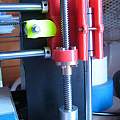
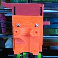
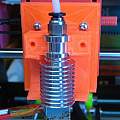
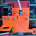
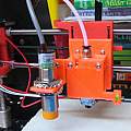
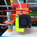
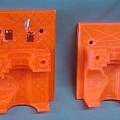
In a perfect world of sharp edges and hard materials, as the printer nozzle hit the bed one could expect one step to move the hot end mount 0.0025 mm and the next to move it 0 mm. Detecting the nozzle hitting the bed comes down to detecting a change in position of 0.0025 mm - at best - more steps give bigger deviations. One could measure the change in position per step, or measure the difference in height between the side of the hot end mount fixed to the X axis and the free side - real world flexibility means that when the nozzle touches the bed the mount starts to bend. Pictures show my E3D V6 Bowden Mount.
My idea was to attach a strain gauge to the hot end mount and measure the change in stress when the nozzle touches the print bed (how much the mount bends). There are similarities to the load cell design [4][5]. A load cell consists of strain gauges fixed to a structure.
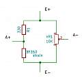
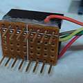
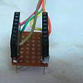
I use a HX711 analogue to digital converter, I only use one BF350 strain gauge so the rest of the Wheatstone resistor bridge is made up of one fixed 330 Ω resistor and a 10K Ω multi-turn potentiometer. The HX711 is read by an Arduino Pro Mini which analyses the data and emulates an end-stop switch. Better results are given by having the HX711 run at 80 Hz rather than 10 Hz. (see Strain Gauge for more details).
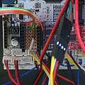
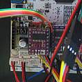
Unfortunately the strain gauge does not provide an absolute reading, strain is relative to something, think of setting the zero point on a weighing scale - so called 'tare'. The load cell design [4][5] uses a G code command to twiddle an output line on the printer processor to indicate "about to home Z axis, please set zero point". Having a printer with a Geeetech 2560 boad, output lines are in short supply, instead I intercepted the step and direction signal lines to the Z axis stepper motor driver. This allows the Pro Mini to know what is going on and improve its interpretation of the data from the strain gauge - for example unless the Z axis is going downwards the end-stop switch should not close.
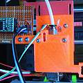
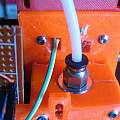
I changed the back part of my E3D V6 Bowden Mount to give a slightly bigger distance between the holes that attach it to the X axis and the plastic that holds the E3D. This gives somewhere to stick the strain gauge and probably makes it a bit more bendable. I decided where to put the strain gauge on the basis of guessing where the part would break if bent enough. The orange material is PETG, I also produced a PLA version with similar results. There are two strain gauges because I damaged the first one whilst fixing it to the mount - see Strain Gauge for more technical details including the HX711.
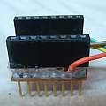
I put the HX711 on a small board attached where the probe usually fits, following a belief that routing analogue signals long distances near lots of electronic noise is a bad idea.
Sample results (comparable with those above):
Mean: 4.384500 Min: 4.370 Max: 4.395 Range: 0.025 Standard Deviation: 0.010943
A common complaint about this sort of probe is that it will damage the bed. I measured the weight applied to the bed by homing onto a weighing scale. The typical weight applied is 30 gm.
Output from the HX711 is far from simple. On power up there is an exponential change (like a capacitor charging), then there is constant noise of amplitude about 3000 (in HX711 un-scaled units). My printer has a Bowden drive, the pressure exerted by the PTFE tube in this on the extruder mount varies with the Z axis position and the effects can be seen in the strain gauge output.
The PTFE pressure varies slowly with position, the noise is independent of position. Contact with the print bed results in a rapid change in strain correlated with Z axis steps. But the change has to be greater than the noise to be seen.
The range value of 0.025 mm (in the test results above) can be understood, the HX711 does 80 samples per second, roughly 12 ms per sample; in that time of 12 ms when homing the Z axis takes 5 (micro) steps, each of which is 0.0025 mm.
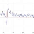
The graph below shows HX711 output (blue) against number of samples for a Marlin homing event (down, touch, up). The red spike is the emulated limit switch output - which is set to trigger at a HX711 value of 6000.
The HX711 has a range of +/ 20 mV, which maps to 24 bits, 1 bit maps to 0.0024 μV. The noise of around 3000 would be about 7.5 μV.
Processing the data consists of ignoring all changes in strain gauge output when the stepper motor is not running. Secondly an exponential moving average (accessible version) is subtracted.
For my purposes results are good enough. Greater accuracy would require a faster analogue to digital converter with less noise, or a mechanical design that produced a larger signal. An alternative HX711 board appeared to be less noisy (see Strain Gauge).
What happened
There is a variable THRESHOLD which sets the value at which the code decides the bed has been touched - it marks the point between the signal and the noise. The temptation is to show off by making it as small as possible. I found it was best to set it well above the noise level. Nothing is lost and results are more reliable.
Most of my 3D printing experience until now has been using the micro-switch that came with the printer for Z axis homing; after a brief spell of "beginner's luck" I spent a lot of time getting poor results with this. I came to the conclusion adjusting it it was non-linear and the value was prone to changing. Automating bed levelling and setting the Z axis position has been a huge improvement.
The snag so far is plastic on the nozzle, which gets dotted on the print bed at the test positions. I found an interesting parallel with the Lulzbot printer that uses electrical conductivity between the nozzle and the bed levelling screws and which people have added auto nozzle wiping to [9].
Given the ATMega 2560 used in many 3D printers has a differential ADC and programmable gain amplifier it might be possible to dispense with the HX711 and Arduino Pro Mini, making a strain gauge Z probe only pennies more expensive than a micro switch.
The video below shows the nozzle homing onto a makeshift balance; the weights are 50 gm and 10 gm, giving an activation force between 50 and 60 gm weight.
https://www.youtube.com/watch?v=K3higvTPbbA
- Arduino project StrainStop04 - 9th July 2017
- OpenSCAD/STL files for modified mount back (5th June 2017)
- Ultimaker E3Dv5 mount with Tilt z-probe
- Smartrap X End Mount For J-Head Light and MK5
- RepRap Prusa i3 bed auto-level
- Reprap Load Cell Z-Probe
- Load Cell Z-Probe Mounts
- Auto bed leveling using piezo discs
- Piezo disk bed leveling for 3D printers
- SONIC 3D PRINTER AUTO BED LEVELING MAKES A SWOOSH
- Lulzbot Mini Dual Wiper
- Precision Piezo
- Duet Delta Smart Effector
- New for RepRap or autobadlevel right on target (strain gauge, Russian blog, 2015)
- QUARTET OF SMD RESISTORS USED TO SENSE Z-AXIS HEIGHT
- 3D PRINTERING: IS HASSLE-FREE BED LEVELING FINALLY HERE?
David Pilling's Wiki
Set view
